11. OPTIONS AND PERIPHERAL EQUIPMENT
11 - 23
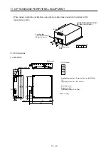
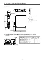
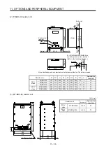
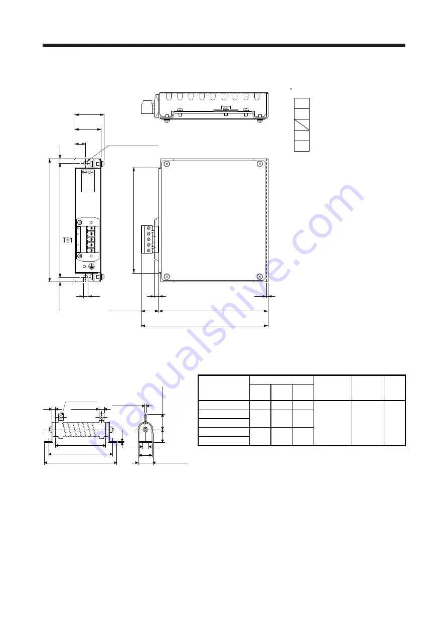
(6) MR-RB1H-4
[Unit: mm]
156
168
144
6
2
149
173
6
Approx. 6
Approx. 24
6
15
φ
6 mounting hole
36
40
TE1 terminal
P
C
G3
G4
Applicable wire size: AWG 24 to 10
Tightening torque: 0.5 to 0.6 [N•m]
Mounting screw
Screw size: M5
Tightening torque: 3.24 [N•m]
Mass: 1.1 [kg]
(7) GRZG400-0.8
Ω
/GRZG400-0.6
Ω
/GRZG400-0.5
Ω
/GRZG400-2.5
Ω
/GRZG400-2.0
Ω
(standard
accessories)
[Unit: mm]
Appr
ox. K
1.6
Approx.
φ
47
9.5
40
411
385
10
Approx.
φ
C
Approx. A
Approx. 2.4
40
Approx. 330
Regenerative
resistor
Variable dimensions
Mounting
screw size
Tightening
torque
[N•m]
Mass
[kg]
A C K
GRZG400-0.8
Ω
10 5.5 39
M8 13.2
0.8
GRZG400-0.6
Ω
16 8.2 46
GRZG400-0.5
Ω
GRZG400-2.5
Ω
10 5.5 39
GRZG400-2.0
Ω
Summary of Contents for MR-J4-100B(-RJ)
Page 17: ...8 MEMO ...
Page 143: ...4 STARTUP 4 20 MEMO ...
Page 199: ...5 PARAMETERS 5 56 MEMO ...
Page 227: ...6 NORMAL GAIN ADJUSTMENT 6 28 MEMO ...
Page 281: ...8 TROUBLESHOOTING 8 16 MEMO ...
Page 303: ...9 DIMENSIONS 9 22 MEMO ...
Page 319: ...10 CHARACTERISTICS 10 16 MEMO ...
Page 429: ...11 OPTIONS AND PERIPHERAL EQUIPMENT 11 110 MEMO ...
Page 435: ...12 ABSOLUTE POSITION DETECTION SYSTEM 12 6 MEMO ...
Page 483: ...14 USING A LINEAR SERVO MOTOR 14 34 MEMO ...
Page 531: ...16 FULLY CLOSED LOOP SYSTEM 16 26 MEMO ...
Page 613: ...17 APPLICATION OF FUNCTIONS 17 82 MEMO ...
Page 654: ...APPENDIX App 41 ...

