1. FUNCTIONS AND CONFIGURATION
1 - 18
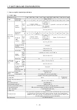
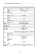
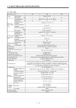
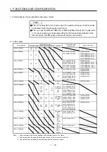
Model: MR-J4-_(-RJ)
10B1
20B1
40B1
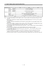
Environment
Ambient
temperature
Operation
0 °C to 55 °C (non-freezing)
Storage
-20 °C to 65 °C (non-freezing)
Ambient
humidity
Operation
5 %RH to 90 %RH (non-condensing)
Storage
Ambience
Indoors (no direct sunlight),
free from corrosive gas, flammable gas, oil mist, dust, and dirt
Altitude
2000 m or less above sea level (Note 9)
Vibration resistance
5.9 m/s
2
, at 10 Hz to 55 Hz (directions of X, Y and Z axes)
Mass
[kg]
0.8
1.0
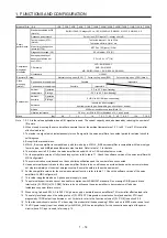
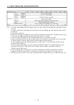
Note 1. 0.3 A is the value applicable when all I/O signals are used. The current capacity can be decreased by reducing the number of
I/O points.
2. When closely mounting the servo amplifiers, operate them at the ambient temperature of 0 °C to 45 °C or at 75% or smaller
effective load ratio.
3. Test pulse is a signal which instantaneously turns off a signal to the servo amplifier at a constant period for external circuit to
self-diagnose.
4. MR-J4-_B servo amplifier is compatible only with two-wire type. MR-J4-_B-RJ servo amplifier is compatible with two-wire type,
four-wire type, and A/B/Z-phase differential output method. Refer to table 1.1 for details.
5. For the compatible version of fully closed loop system, refer to table 1.1. Check the software version of the servo amplifier with
MR Configurator2.
6 The communication cycle depends on the controller specifications and the number of axes connected.
7. For the compatible version for the scale measurement function, refer to table 1.1. Check the software version of the servo
amplifier with MR Configurator2.
8. The safety level depends on the setting value of [Pr. PF18 STO diagnosis error detection time] and whether STO input
diagnosis by TOFB output is performed or not. For details, refer to the Function column of [Pr. PF18] in section 5.2.6.
9. Follow the restrictions in section 2.7 when using this product at altitude exceeding 1000 m and up to 2000 m above sea level.
Summary of Contents for MR-J4-100B(-RJ)
Page 17: ...8 MEMO ...
Page 143: ...4 STARTUP 4 20 MEMO ...
Page 199: ...5 PARAMETERS 5 56 MEMO ...
Page 227: ...6 NORMAL GAIN ADJUSTMENT 6 28 MEMO ...
Page 281: ...8 TROUBLESHOOTING 8 16 MEMO ...
Page 303: ...9 DIMENSIONS 9 22 MEMO ...
Page 319: ...10 CHARACTERISTICS 10 16 MEMO ...
Page 429: ...11 OPTIONS AND PERIPHERAL EQUIPMENT 11 110 MEMO ...
Page 435: ...12 ABSOLUTE POSITION DETECTION SYSTEM 12 6 MEMO ...
Page 483: ...14 USING A LINEAR SERVO MOTOR 14 34 MEMO ...
Page 531: ...16 FULLY CLOSED LOOP SYSTEM 16 26 MEMO ...
Page 613: ...17 APPLICATION OF FUNCTIONS 17 82 MEMO ...
Page 654: ...APPENDIX App 41 ...

