15. USING A DIRECT DRIVE MOTOR
15 - 11
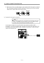
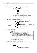
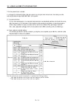
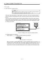
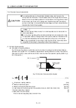
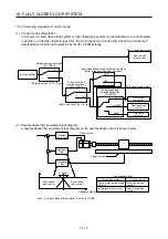
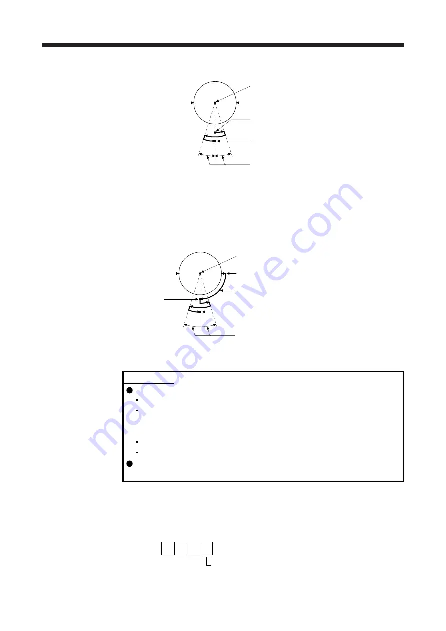
2) Direct drive motor movement (when FLS and RLS are on)
Magnetic pole detection completion position
Servo-on position (Magnetic pole detection start position)
Center of direct drive motor rotation part
FLS (Note)
(Note) RLS
10 degrees or less
Note. When you turn off FLS (Upper stroke limit) or RLS (Lower stroke limit) during the
magnetic pole detection, the magnetic pole detection is carried on to the opposite
direction. When FLS and RLS are off, [AL. 27 Initial magnetic pole detection error]
occurs.
3) Direct drive motor movement (when FLS or RLS is off)
When FLS or RLS is off at servo-on, the magnetic pole detection is carried out as follows.
Magnetic pole detection completion position
Magnetic pole detection
start position
After the machine moves to the position where the stroke limit
(FLS or RLS) is set, the magnetic pole detection starts.
Servo-on position
Center of direct drive motor rotation part
FLS
RLS
10 degrees or less
(b) Absolute position detection system
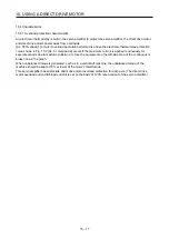
POINT
The magnetic pole detection is required in the following timings.
When the system is set up (at the first startup of equipment)
When the Z-phase pulse of the direct drive motor is not turned on at the
system setup (When the Z-phase pulse of the direct drive motor can be turned
on manually, the magnetic pole detection is not required.)
After a direct drive motor is replaced
When [AL. 25 Absolute position erased] has occurred
Turn on the Z-phase pulse of the direct drive motor in JOG operation from the
controller after the magnetic pole detection.
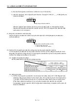
Perform the magnetic pole detection in the following procedure.
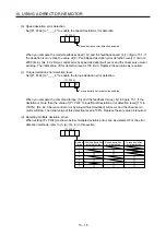
1) Set [Pr. PL01 Linear servo motor/DD motor function selection 1] to "_ _ _ 1" (Magnetic pole
detection at first servo-on).
[Pr. PL01]
Magnetic pole detection at first servo-on (initial value)
1
Summary of Contents for MR-J4-100B(-RJ)
Page 17: ...8 MEMO ...
Page 143: ...4 STARTUP 4 20 MEMO ...
Page 199: ...5 PARAMETERS 5 56 MEMO ...
Page 227: ...6 NORMAL GAIN ADJUSTMENT 6 28 MEMO ...
Page 281: ...8 TROUBLESHOOTING 8 16 MEMO ...
Page 303: ...9 DIMENSIONS 9 22 MEMO ...
Page 319: ...10 CHARACTERISTICS 10 16 MEMO ...
Page 429: ...11 OPTIONS AND PERIPHERAL EQUIPMENT 11 110 MEMO ...
Page 435: ...12 ABSOLUTE POSITION DETECTION SYSTEM 12 6 MEMO ...
Page 483: ...14 USING A LINEAR SERVO MOTOR 14 34 MEMO ...
Page 531: ...16 FULLY CLOSED LOOP SYSTEM 16 26 MEMO ...
Page 613: ...17 APPLICATION OF FUNCTIONS 17 82 MEMO ...
Page 654: ...APPENDIX App 41 ...

