3
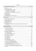
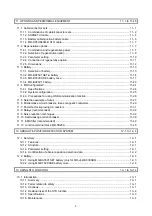
6.2.2 Display transition and operation procedure of one-touch tuning ............................................... 6- 7
6.2.3 Caution for one-touch tuning ..................................................................................................... 6-17
6.3 Auto tuning ....................................................................................................................................... 6-18
6.3.1 Auto tuning mode ...................................................................................................................... 6-18
6.3.2 Auto tuning mode basis ............................................................................................................. 6-19
6.3.3 Adjustment procedure by auto tuning ....................................................................................... 6-20
6.3.4 Response level setting in auto tuning mode ............................................................................. 6-21
6.4 Manual mode ................................................................................................................................... 6-22
6.5 2 gain adjustment mode .................................................................................................................. 6-25
7. SPECIAL ADJUSTMENT FUNCTIONS
7- 1 to 7-32
7.1 Filter setting ...................................................................................................................................... 7- 1
7.1.1 Machine resonance suppression filter ....................................................................................... 7- 2
7.1.2 Adaptive filter II ........................................................................................................................... 7- 5
7.1.3 Shaft resonance suppression filter ............................................................................................. 7- 7
7.1.4 Low-pass filter ............................................................................................................................ 7- 8
7.1.5 Advanced vibration suppression control II ................................................................................. 7- 8
7.1.6 Command notch filter ................................................................................................................ 7-13
7.2 Gain switching function .................................................................................................................... 7-15
7.2.1 Applications ............................................................................................................................... 7-15
7.2.2 Function block diagram ............................................................................................................. 7-16
7.2.3 Parameter
.................................................................................................................................. 7-17
7.2.4 Gain switching procedure ......................................................................................................... 7-20
7.3 Tough drive function ........................................................................................................................ 7-24
7.3.1 Vibration tough drive function.................................................................................................... 7-24
7.3.2 Instantaneous power failure tough drive function ..................................................................... 7-26
7.4 Compliance with SEMI-F47 standard .............................................................................................. 7-30
7.5 Model adaptive control disabled ...................................................................................................... 7-32
8. TROUBLESHOOTING
8- 1 to 8-16
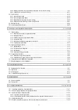
8.1 Explanation for the lists ..................................................................................................................... 8- 1
8.2 Alarm list ........................................................................................................................................... 8- 2
8.3 Warning list ...................................................................................................................................... 8-12
8.4 Troubleshooting at power on ........................................................................................................... 8-15
9. DIMENSIONS
9- 1 to 9- 6
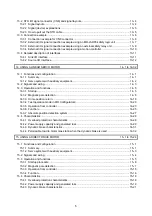
9.1 Servo amplifier .................................................................................................................................. 9- 1
9.2 Connector ......................................................................................................................................... 9- 4
10. CHARACTERISTICS
10- 1 to 10-10
10.1 Overload protection characteristics .............................................................................................. 10- 1
10.2 Power supply capacity and generated loss .................................................................................. 10- 2
10.3 Dynamic brake characteristics ...................................................................................................... 10- 5
10.3.1 Dynamic brake operation ....................................................................................................... 10- 6
10.3.2 Permissible load to motor inertia when the dynamic brake is used ....................................... 10- 8
10.4 Cable bending life ......................................................................................................................... 10- 9
10.5 Inrush currents at power-on of main circuit and control circuit ..................................................... 10- 9
Summary of Contents for MR-J4W2-0303B6
Page 39: ...2 INSTALLATION 2 8 MEMO ...
Page 97: ...4 STARTUP 4 20 MEMO ...
Page 181: ...6 NORMAL GAIN ADJUSTMENT 6 28 MEMO ...
Page 235: ...9 DIMENSIONS 9 6 MEMO ...
Page 245: ...10 CHARACTERISTICS 10 10 MEMO ...
Page 309: ...13 USING STO FUNCTION 13 14 MEMO ...
Page 365: ...15 USING A DIRECT DRIVE MOTOR 15 24 MEMO ...
Page 389: ...16 FULLY CLOSED LOOP SYSTEM 16 24 MEMO ...
Page 461: ...17 APPLICATION OF FUNCTIONS 17 72 MEMO ...
Page 556: ...APPENDIX App 41 ...
Page 585: ...MEMO ...


