6
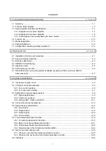
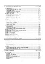
16. FULLY CLOSED LOOP SYSTEM
16- 1 to 16-24
16.1 Functions and configuration ......................................................................................................... 16- 1
16.1.1 Function block diagram .......................................................................................................... 16- 1
16.1.2 Selecting procedure of control mode ..................................................................................... 16- 3
16.1.3 System configuration
.............................................................................................................. 16- 4
16.2 Load-side encoder ........................................................................................................................ 16- 5
16.2.1 Linear encoder ....................................................................................................................... 16- 5
16.2.2 Rotary encoder
....................................................................................................................... 16- 5
16.2.3 Configuration diagram of encoder cable ................................................................................ 16- 5
16.2.4 MR-J4FCCBL03M branch cable ............................................................................................ 16- 6
16.3 Operation and functions ................................................................................................................ 16- 7
16.3.1 Startup .................................................................................................................................... 16- 7
16.3.2 Home position return ............................................................................................................. 16-14
16.3.3 Operation from controller ...................................................................................................... 16-17
16.3.4 Fully closed loop control error detection functions................................................................ 16-19
16.3.5 Auto tuning function .............................................................................................................. 16-20
16.3.6 Machine analyzer function .................................................................................................... 16-20
16.3.7 Test operation mode ............................................................................................................. 16-20
16.3.8 Absolute position detection system under fully closed loop system ..................................... 16-21
16.3.9 About MR Configurator2 ....................................................................................................... 16-22
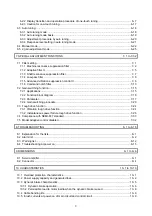
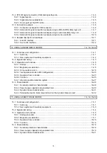
17. APPLICATION OF FUNCTIONS
17- 1 to 17-72
17.1 J3 compatibility mode ................................................................................................................... 17- 1
17.1.1 Outline of J3 compatibility mode ............................................................................................ 17- 1
17.1.2 Operation modes supported by J3 compatibility mode .......................................................... 17- 1
17.1.3 J3 compatibility mode supported function list ........................................................................ 17- 2
17.1.4 How to switch J4 mode/J3 compatibility mode ...................................................................... 17- 5
17.1.5 How to use the J3 compatibility mode ................................................................................... 17- 6
17.1.6 Cautions for switching J4 mode/J3 compatibility mode ......................................................... 17- 7
17.1.7 Cautions for the J3 compatibility mode .................................................................................. 17- 7
17.1.8 Change of specifications of "J3 compatibility mode" switching process ................................ 17- 9
17.1.9 J3 extension function ............................................................................................................ 17-11
17.2 Scale measurement function ....................................................................................................... 17-65
17.2.1 Functions and configuration .................................................................................................. 17-65
17.2.2 Scale measurement encoder ................................................................................................ 17-67
17.2.3 How to use scale measurement function .............................................................................. 17-70
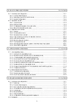
18. MR-J4W2-0303B6 SERVO AMPLIFIER
18- 1 to 18-54
18.1 Functions and configuration ......................................................................................................... 18- 1
18.1.1 Summary ................................................................................................................................ 18- 1
18.1.2 Function block diagram .......................................................................................................... 18- 2
18.1 3 Servo amplifier standard specifications ................................................................................. 18- 3
18.1.4 Combinations of servo amplifiers and servo motors .............................................................. 18- 4
18.1.5 Function list ............................................................................................................................ 18- 5
18.1.6 Model definition ...................................................................................................................... 18- 7
18.1.7 Parts identification .................................................................................................................. 18- 8
18.1.8 Configuration including peripheral equipment ....................................................................... 18- 9
18.2 Installation .................................................................................................................................... 18-10
Summary of Contents for MR-J4W2-0303B6
Page 39: ...2 INSTALLATION 2 8 MEMO ...
Page 97: ...4 STARTUP 4 20 MEMO ...
Page 181: ...6 NORMAL GAIN ADJUSTMENT 6 28 MEMO ...
Page 235: ...9 DIMENSIONS 9 6 MEMO ...
Page 245: ...10 CHARACTERISTICS 10 10 MEMO ...
Page 309: ...13 USING STO FUNCTION 13 14 MEMO ...
Page 365: ...15 USING A DIRECT DRIVE MOTOR 15 24 MEMO ...
Page 389: ...16 FULLY CLOSED LOOP SYSTEM 16 24 MEMO ...
Page 461: ...17 APPLICATION OF FUNCTIONS 17 72 MEMO ...
Page 556: ...APPENDIX App 41 ...
Page 585: ...MEMO ...


