6. NORMAL GAIN ADJUSTMENT
6 - 27
(4) Parameter adjustment
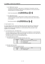
[Pr. PB07 Model loop gain]
This parameter determines the response level of the position control loop. Increasing the value improves
trackability to a position command, but a too high value will make overshoot liable to occur at settling.
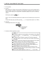
Number of droop pulses is determined by the following expression.
Number of droop pulses [pulse] =
Model loop gain setting
Position command frequency [pulse/s]
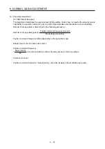
Position command frequency differs depending on the operation mode.
Rotary servo motor and direct drive motor:
Position command frequency
=
Speed [r/min]
60
× Encoder resolution (number of pulses per servo motor revolution)
Linear servo motor:
Position command frequency = Speed [mm/s] ÷ Encoder resolution (travel distance per pulse)
Summary of Contents for MR-J4W2-0303B6
Page 39: ...2 INSTALLATION 2 8 MEMO ...
Page 97: ...4 STARTUP 4 20 MEMO ...
Page 181: ...6 NORMAL GAIN ADJUSTMENT 6 28 MEMO ...
Page 235: ...9 DIMENSIONS 9 6 MEMO ...
Page 245: ...10 CHARACTERISTICS 10 10 MEMO ...
Page 309: ...13 USING STO FUNCTION 13 14 MEMO ...
Page 365: ...15 USING A DIRECT DRIVE MOTOR 15 24 MEMO ...
Page 389: ...16 FULLY CLOSED LOOP SYSTEM 16 24 MEMO ...
Page 461: ...17 APPLICATION OF FUNCTIONS 17 72 MEMO ...
Page 556: ...APPENDIX App 41 ...
Page 585: ...MEMO ...


