11. OPTIONS AND PERIPHERAL EQUIPMENT
11 - 7
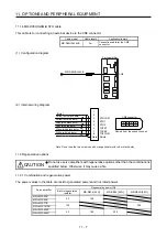
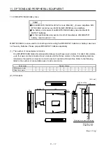
11.1.4 MR-D05UDL3M-B STO cable
This cable is for connecting an external device to the CN8 connector.
Cable model
Cable length Application/remark
MR-D05UDL3M-B 3
m
Connection cable for the CN8
connector
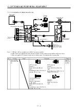
(1) Configuration diagram
MR-D05UDL3M-B
CN8
Servo amplifier
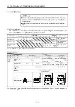
(2) Internal wiring diagram
1
2
3
6
7
Plate
STO2
TOFB1
TOFB2
Shield
STO1
TOFCOM
8
4
5
STOCOM
Yellow (with black dots)
Yellow (with red dots)
Gray (with black dots)
Gray (with red dots)
White (with black dots)
White (with red dots)
(Note)
2
1
6
4
8
CN8 connector
3
5
7
Viewed from the connection part
Note. Do not use the two core wires with orange sheath (with red or black dots).
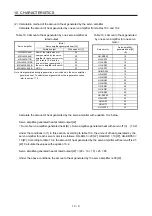
11.2 Regenerative options
CAUTION
Do not use servo amplifiers with regenerative options other than the combinations
specified below. Otherwise, it may cause a fire.
11.2.1 Combination and regenerative power
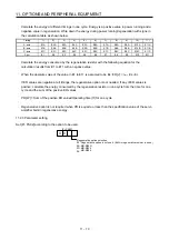
The power values in the table are resistor-generated powers and not rated powers.
Servo amplifier
Regenerative power [W]
Built-in regenerative
resistor
MR-RB14 [26
Ω
] MR-RB34
[26
Ω
] MR-RB3N
[26
Ω
]
MR-J4W2-22B
20 100
MR-J4W2-44B
MR-J4W2-77B
100
300
MR-J4W2-1010B
MR-J4W3-222B
30 100 300
MR-J4W3-444B
Summary of Contents for MR-J4W2-0303B6
Page 39: ...2 INSTALLATION 2 8 MEMO ...
Page 97: ...4 STARTUP 4 20 MEMO ...
Page 181: ...6 NORMAL GAIN ADJUSTMENT 6 28 MEMO ...
Page 235: ...9 DIMENSIONS 9 6 MEMO ...
Page 245: ...10 CHARACTERISTICS 10 10 MEMO ...
Page 309: ...13 USING STO FUNCTION 13 14 MEMO ...
Page 365: ...15 USING A DIRECT DRIVE MOTOR 15 24 MEMO ...
Page 389: ...16 FULLY CLOSED LOOP SYSTEM 16 24 MEMO ...
Page 461: ...17 APPLICATION OF FUNCTIONS 17 72 MEMO ...
Page 556: ...APPENDIX App 41 ...
Page 585: ...MEMO ...

