11. OPTIONS AND PERIPHERAL EQUIPMENT
11 - 10
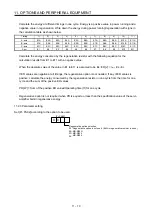
Calculate the energy at different timings in one cycle. Energy is a positive value in power running and a
negative value in regeneration. Write down the energy during power running/regeneration with signs in
the calculation table as shown below.
Timing
1) 2) 3) 4) 5) 6) 7) 8) 9) 10)
11)
A-axis
E1A E2A E3A E4A E5A E6A E7A E8A E9A E10A
E11A
B-axis
E1B E2B E3B E4B E5B E6B E7B E8B E9B E10B
E11B
C-axis
E1C E2C E3C E4C E5C E6C E7C E8C E9C E10C
E11C
Sum
E1 E2 E3 E4 E5 E6 E7 E8 E9 E10
E11
Calculate the energy consumed by the regenerative resistor with the following equation for the
calculation results from E1 to E11 with a negative value.
When the absolute value of the value in E1 to E11 is assumed to be Es: ER [J] =
η
m
• Es - Ec
If ER values are negative at all timings, the regenerative option is not needed. If any of ER values is
positive, calculate the energy consumed by the regenerative resistor in one cycle from the time for one
cycle and the sum of the positive ER values.
PR [W] = Sum of the positive ER values/Operating time (tf) for one cycle
Regenerative option is not required when PR is equal to or less than the specification value of the servo
amplifier built-in regenerative energy.
11.2.3 Parameter setting
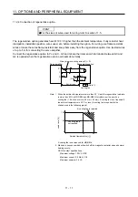
Set [Pr. PA02] according to the option to be used.
Regenerative option selection
00
0B
0D
0E
: Regenerative option is not used. (Built-in regenerative resistor is used.)
: MR-RB3N
: MR-RB14
: MR-RB34
0 0
[Pr. PA02]
Summary of Contents for MR-J4W2-0303B6
Page 39: ...2 INSTALLATION 2 8 MEMO ...
Page 97: ...4 STARTUP 4 20 MEMO ...
Page 181: ...6 NORMAL GAIN ADJUSTMENT 6 28 MEMO ...
Page 235: ...9 DIMENSIONS 9 6 MEMO ...
Page 245: ...10 CHARACTERISTICS 10 10 MEMO ...
Page 309: ...13 USING STO FUNCTION 13 14 MEMO ...
Page 365: ...15 USING A DIRECT DRIVE MOTOR 15 24 MEMO ...
Page 389: ...16 FULLY CLOSED LOOP SYSTEM 16 24 MEMO ...
Page 461: ...17 APPLICATION OF FUNCTIONS 17 72 MEMO ...
Page 556: ...APPENDIX App 41 ...
Page 585: ...MEMO ...


