15. USING A DIRECT DRIVE MOTOR
15 - 6
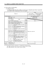
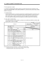
15.3.1 Startup procedure
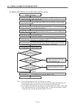
Start up the direct drive servo system in the following procedure.
Absolute position detection system
Installation and wiring
Turn on the Z-phase pulse of the
direct drive motor by using the JOG
operation. (Notes 1 and 2)
Execute the magnetic pole detection. (Refer to section 15.3.2.) (Note 1)
Absolute position
detection system?
Incremental system
Can you manually turn
on the Z-phase pulse of the
direct drive motor?
Change the setting to disable the
magnetic pole detection.
(Refer to section 15.3.2.)
Turn on the Z-phase pulse of the
direct drive motor manually. (Note 3)
Turn the servo amplifier power
supply off and on again. (Note 2)
Positioning operation check using the test operation mode (Note 1)
Positioning operation check using the controller (Refer to section 15.3.3.)
Home position return operation (Refer to the controller manual used.)
Positioning operation
No
Yes
Perform this procedure once at startup.
Set [Pr. PA01]. (Refer to section 3.14.)
Note 1. Use MR Configurator2.
2. For the absolute position detection system, always turn on the Z-phase pulse of the direct drive motor while the servo amplifier
power is on, and then turn the servo amplifier power supply off and on again. By turning off and on the power supply, the
absolute position becomes confirmed. Without this operation, the absolute position will not be regained properly, and a
warning will occur at the controller.
3. If the Z-phase pulse of the direct drive motor can be turned on manually, the Z-phase pulse does not have to be turned on by
the magnetic pole detection or the JOG operation.
For this operation, always connect the direct drive motor encoder and the servo amplifier, and turn on only the control circuit
power supply of the servo amplifier (L11/L21) (turn off the main circuit power supply L1, L2, and L3). Perform this operation by
considering the safety.
Summary of Contents for MR-J4W2-0303B6
Page 39: ...2 INSTALLATION 2 8 MEMO ...
Page 97: ...4 STARTUP 4 20 MEMO ...
Page 181: ...6 NORMAL GAIN ADJUSTMENT 6 28 MEMO ...
Page 235: ...9 DIMENSIONS 9 6 MEMO ...
Page 245: ...10 CHARACTERISTICS 10 10 MEMO ...
Page 309: ...13 USING STO FUNCTION 13 14 MEMO ...
Page 365: ...15 USING A DIRECT DRIVE MOTOR 15 24 MEMO ...
Page 389: ...16 FULLY CLOSED LOOP SYSTEM 16 24 MEMO ...
Page 461: ...17 APPLICATION OF FUNCTIONS 17 72 MEMO ...
Page 556: ...APPENDIX App 41 ...
Page 585: ...MEMO ...

