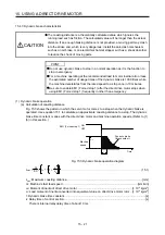
16. FULLY CLOSED LOOP SYSTEM
16 - 3
16.1.2 Selecting procedure of control mode
(1) Control mode configuration
In this servo, a semi closed loop system or fully closed loop system can be selected as a control system.
In addition, on the fully closed loop system, the semi closed loop control, fully closed loop control and
dual feedback control can be selected by the [Pr. PE08] settings.
"4500"
"0"
Fully closed loop
function selection 1
([Pr. PE01])
Operation mode selection
([Pr. PA01])
"_ _ _ 1"
"_ _ _ 0"
Fully closed
loop control
Semi closed
loop control
"_ _ 0 _"
Servo amplifier
"_ _ 1 _"
(Refer to section 16.3.1 (2) (a))
Semi closed/fully closed switching command
(Refer to the controller user's manual.)
OFF
ON
(Refer to section 16.3.1 (2) (b))
Dual feedback
control
Semi closed
loop control
"1 to 4499"
Fully closed loop system
Fully closed loop
dual feedback filter
([Pr. PE08])
Semi closed loop system
(2) Dual feedback filter equivalent block diagram
A dual feedback filter equivalent block diagram on the dual feedback control is shown below.
Servo motor during a stop
Fully closed loop
control
Semi closed loop
control
Semi closed
loop control
Fully closed
loop control
+
+
+
-
Dual feedback filter
Servo motor
Linear encoder
Position
control unit
High-pass
filter
Low-pass
filter
Frequency [rad/s]
Operation status
Control status
Note. Set "
ω
" (a dual feedback filter band) with [Pr. PE08].
Summary of Contents for MR-J4W2-0303B6
Page 39: ...2 INSTALLATION 2 8 MEMO ...
Page 97: ...4 STARTUP 4 20 MEMO ...
Page 181: ...6 NORMAL GAIN ADJUSTMENT 6 28 MEMO ...
Page 235: ...9 DIMENSIONS 9 6 MEMO ...
Page 245: ...10 CHARACTERISTICS 10 10 MEMO ...
Page 309: ...13 USING STO FUNCTION 13 14 MEMO ...
Page 365: ...15 USING A DIRECT DRIVE MOTOR 15 24 MEMO ...
Page 389: ...16 FULLY CLOSED LOOP SYSTEM 16 24 MEMO ...
Page 461: ...17 APPLICATION OF FUNCTIONS 17 72 MEMO ...
Page 556: ...APPENDIX App 41 ...
Page 585: ...MEMO ...


