16. FULLY CLOSED LOOP SYSTEM
16 - 12
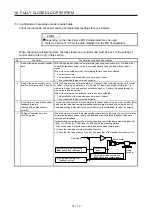
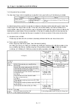
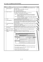
(5) Confirmation of load-side encoder position data
Check the load-side encoder mounting and parameter settings for any problems.
POINT
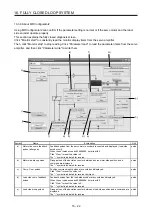
Depending on the check items, MR Configurator2 may be used.
Refer to section 16.3.6 for the data displayed on the MR Configurator2.
When checking the following items, the fully closed loop control mode must be set. For the setting of
control mode, refer to (2) in this section.
No.
Check item
Confirmation method and description
1
Read of load-side encoder position
data
With the load-side encoder in a normal state (mounting, connection, etc.), the load-side
cumulative feedback pulses value is counted normally when the load-side encoder is
moved.
When it is not counted normally, the following factors can be considered.
1. An alarm occurred.
2. The installation of the load-side encoder was not correct.
3. The encoder cable was not wired correctly.
2
Read of load-side encoder home
position (reference mark, Z-phase)
With the home position (reference mark, or Z-phase) of the load-side encoder in a normal
condition (mounting, connection, etc.), the value of load-side encoder information 1 is
cleared to 0 when the home position (reference mark, or Z-phase) is passed through by
moving the load-side encoder.
When it is not cleared, the following factors can be considered.
1. The installation of the load-side encoder was not correct.
2. The encoder cable was not wired correctly.
3
Confirmation of load-side encoder
feedback direction
(Setting of load-side encoder
polarity)
Confirm that the directions of the cumulative feedback pulses of servo motor encoder (after
gear) and the load-side cumulative feedback pulses are matched by moving the device
(load-side encoder) manually in the servo-off status. If mismatched, reverse the polarity.
4
Setting of load-side encoder
electronic gear
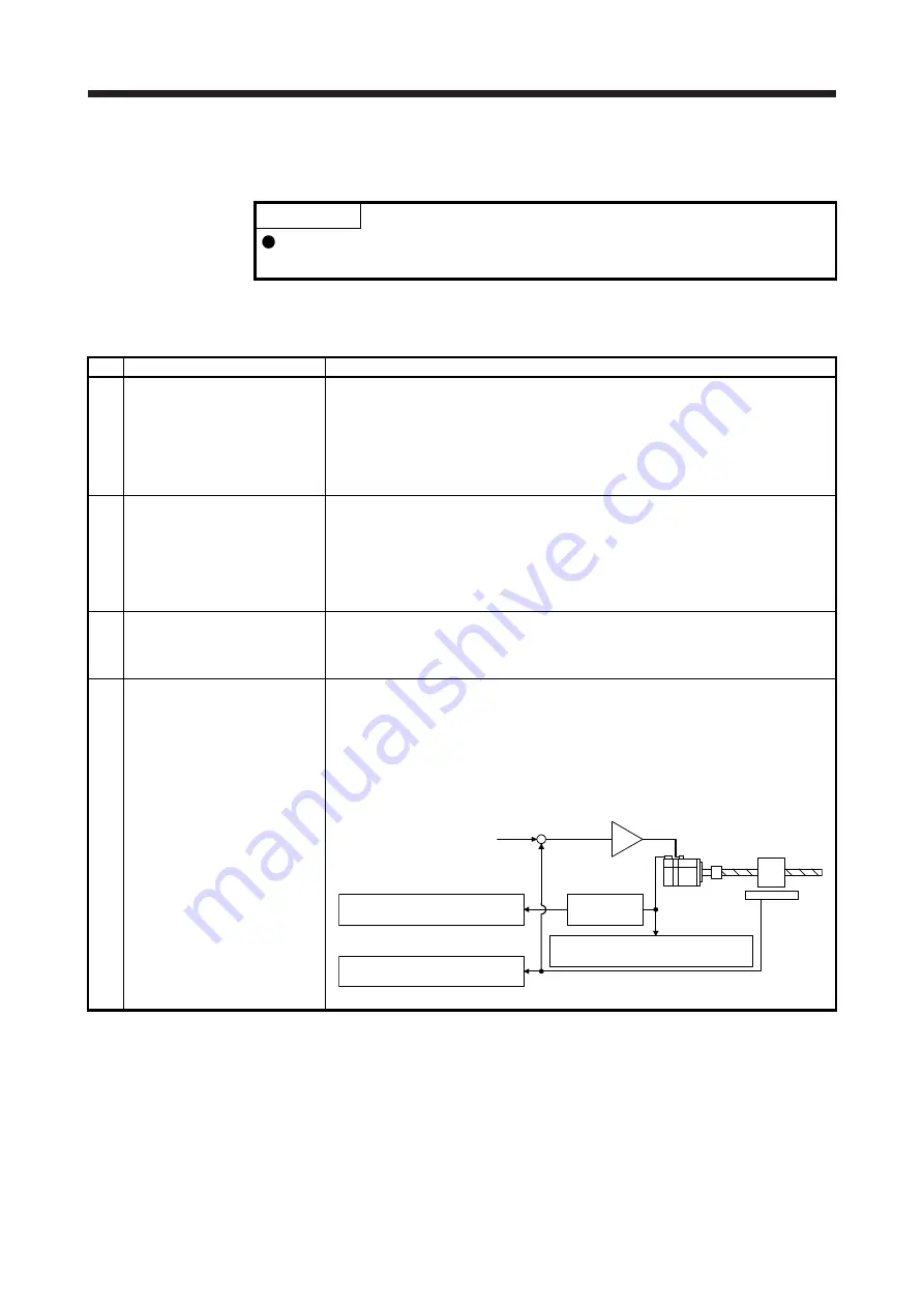
When the servo motor and load-side encoder operate synchronously, the servo motor-side
cumulative feedback pulses (after gear) and load-side cumulative feedback pulses are
matched and increased.
If mismatched, review the setting of fully closed loop control feedback electronic gear ([Pr.
PE04], [Pr. PE05], [Pr. PE34], and [Pr. PE35]) with the following method.
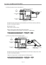
1) Check the servo motor-side cumulative feedback pulses (before gear).
2) Check the load-side cumulative feedback pulses.
3) Check that the ratio of above 1) and 2) has been that of the feedback electronic gear.
Servo motor
Linear
encoder
+
-
Servo motor-side cumulative
feedback pulses (after gear)
3) Electronic
gear
2) Load-side cumulative
feedback pulses
Command
1) Servo motor-side cumulative
feedback pulses (before gear)
Summary of Contents for MR-J4W2-0303B6
Page 39: ...2 INSTALLATION 2 8 MEMO ...
Page 97: ...4 STARTUP 4 20 MEMO ...
Page 181: ...6 NORMAL GAIN ADJUSTMENT 6 28 MEMO ...
Page 235: ...9 DIMENSIONS 9 6 MEMO ...
Page 245: ...10 CHARACTERISTICS 10 10 MEMO ...
Page 309: ...13 USING STO FUNCTION 13 14 MEMO ...
Page 365: ...15 USING A DIRECT DRIVE MOTOR 15 24 MEMO ...
Page 389: ...16 FULLY CLOSED LOOP SYSTEM 16 24 MEMO ...
Page 461: ...17 APPLICATION OF FUNCTIONS 17 72 MEMO ...
Page 556: ...APPENDIX App 41 ...
Page 585: ...MEMO ...


