17. APPLICATION OF FUNCTIONS
17 - 59
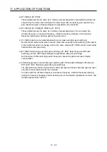
(b) Instantaneous power failure tough drive function
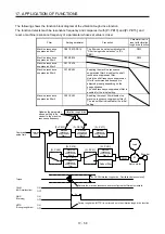
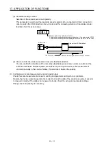
The instantaneous power failure tough drive function avoids [AL. 10 Undervoltage] even when an
instantaneous power failure occurs during operation. When the instantaneous power failure tough
drive activates, the function will increase the immunity to instantaneous power failures using the
electrical energy charged in the capacitor in the servo amplifier and will change an alarm level of
[AL. 10 Undervoltage] simultaneously. The [AL. 10.1 Voltage drop in the control circuit power]
detection time for the control circuit power supply can be changed by [Pr. PX28 SEMI-F47 function -
Instantaneous power failure detection time]. In addition, [AL. 10.2 Voltage drop in the main circuit
power] detection level for the bus voltage is changed automatically.
POINT
MBR (Electromagnetic brake interlock) will not turn off during the instantaneous
power failure tough drive.
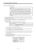
When the load of instantaneous power failure is large, [AL. 10.2] caused by the
bus voltage drop may occur regardless of the set value of [Pr. PX28 SEMI-F47
function - Instantaneous power failure detection time].
The MR-J4W2-0303B6 servo amplifier is not compatible with instantaneous
power failure tough drive.
The setting range of [Pr. PX28 SEMI-F47 function - Instantaneous power failure
detection time] differs depending on the software version of the servo amplifier
as follows.
Software version C0 or later: Setting range 30 ms to 200 ms
Software version C1 or earlier: Setting range 30 ms to 500 ms
To comply with SEMI-F47 standard, it is unnecessary to change the initial value
(200 ms).
However, when the instantaneous power failure time exceeds 200 ms, and the
instantaneous power failure voltage is less than 70% of the rated input voltage,
the power may be normally turned off even if a value larger than 200 ms is set in
the parameter.
Summary of Contents for MR-J4W2-0303B6
Page 39: ...2 INSTALLATION 2 8 MEMO ...
Page 97: ...4 STARTUP 4 20 MEMO ...
Page 181: ...6 NORMAL GAIN ADJUSTMENT 6 28 MEMO ...
Page 235: ...9 DIMENSIONS 9 6 MEMO ...
Page 245: ...10 CHARACTERISTICS 10 10 MEMO ...
Page 309: ...13 USING STO FUNCTION 13 14 MEMO ...
Page 365: ...15 USING A DIRECT DRIVE MOTOR 15 24 MEMO ...
Page 389: ...16 FULLY CLOSED LOOP SYSTEM 16 24 MEMO ...
Page 461: ...17 APPLICATION OF FUNCTIONS 17 72 MEMO ...
Page 556: ...APPENDIX App 41 ...
Page 585: ...MEMO ...

