17. APPLICATION OF FUNCTIONS
17 - 68
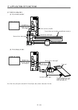
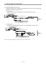
(3) Configuration diagram of encoder cable
Configuration diagram for servo amplifier and scale measurement encoder is shown below. Cables vary
depending on the scale measurement encoder.
(a) Linear encoder
Refer to "Linear Encoder Instruction Manual" for encoder cables for linear encoder.
Servo amplifier
Linear encoder
CN2A
CN2B
MR-J4FCCBL03M branch cable
(Refer to section 16.2.4.)
Encoder of rotary servo motor
Encoder cable
(Refer to "Linear Encoder Instruction Manual".)
CN2
MOTOR
SCALE
Scale
measurement
encoder
(b) Rotary encoder
Refer to "Servo Motor Instruction Manual (Vol. 3)" for encoder cables for rotary encoders.
Servo amplifier
CN2A
CN2B
MR-J4FCCBL03M branch cable
(Refer to section 16.2.4.)
Encoder of rotary servo motor
Encoder cable
(Refer to "Servo Motor Instruction Manual (Vol. 3)".)
CN2
MOTOR
SCALE
(Note)
Scale
measurement
encoder
Servo motor
HG-KR
HG-MR
(Note)
Note. Use a two-wire type encoder cable. A four-wire type linear encoder cable cannot be used.
Summary of Contents for MR-J4W2-0303B6
Page 39: ...2 INSTALLATION 2 8 MEMO ...
Page 97: ...4 STARTUP 4 20 MEMO ...
Page 181: ...6 NORMAL GAIN ADJUSTMENT 6 28 MEMO ...
Page 235: ...9 DIMENSIONS 9 6 MEMO ...
Page 245: ...10 CHARACTERISTICS 10 10 MEMO ...
Page 309: ...13 USING STO FUNCTION 13 14 MEMO ...
Page 365: ...15 USING A DIRECT DRIVE MOTOR 15 24 MEMO ...
Page 389: ...16 FULLY CLOSED LOOP SYSTEM 16 24 MEMO ...
Page 461: ...17 APPLICATION OF FUNCTIONS 17 72 MEMO ...
Page 556: ...APPENDIX App 41 ...
Page 585: ...MEMO ...


