18. MR-J4W2-0303B6 SERVO AMPLIFIER
18 - 30
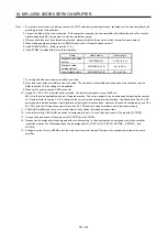
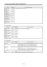
(5) Analog monitor output
Signal name
Symbol
Connector
pin No.
Function and application
I/O
division
Analog monitor 1
MO1
CN3-2
This is used to output the data set in [Pr. PC09] to between MO1 and LG in
terms of voltage.
Output voltage: 10 V ± 5 V
Resolution: 10 bits or equivalent
Analog
output
Analog monitor 2
MO2
CN3-15
This signal outputs the data set in [Pr. PC10] to between MO2 and LG in
terms of voltage.
Output voltage: 10 V ± 5 V
Resolution: 10 bits or equivalent
Analog
output
(6) Analog monitor
POINT
A voltage of analog monitor output may be irregular at power-on.
The servo status can be outputted to two channels in terms of voltage.
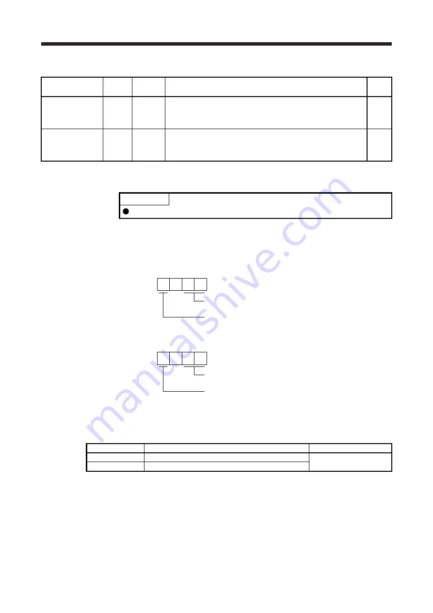
(a) Setting
Change the following digits of [Pr. PC09] and [Pr. PC10].
Analog monitor 1 output selection
(the signal provided to the output across MO1 and LG)
0
[Pr. PC09]
Analog monitor 1 output axis selection
0: A-axis
1: B-axis
Analog monitor 2 output selection
(the signal provided to the output across MO2 and LG)
0
[Pr. PC10]
Analog monitor 2 output axis selection
0: A-axis
1: B-axis
[Pr. PC11] and [Pr. PC12] can be used to set the offset voltages to the analog output voltages.
Setting value is -9999 mV to 9999 mV.
Parameter
Description
Setting range [mV]
PC11
Set the offset voltage of MO1 (Analog monitor 1).
-9999 to 9999
PC12
Set the offset voltage of MO2 (Analog monitor 2).
Summary of Contents for MR-J4W2-0303B6
Page 39: ...2 INSTALLATION 2 8 MEMO ...
Page 97: ...4 STARTUP 4 20 MEMO ...
Page 181: ...6 NORMAL GAIN ADJUSTMENT 6 28 MEMO ...
Page 235: ...9 DIMENSIONS 9 6 MEMO ...
Page 245: ...10 CHARACTERISTICS 10 10 MEMO ...
Page 309: ...13 USING STO FUNCTION 13 14 MEMO ...
Page 365: ...15 USING A DIRECT DRIVE MOTOR 15 24 MEMO ...
Page 389: ...16 FULLY CLOSED LOOP SYSTEM 16 24 MEMO ...
Page 461: ...17 APPLICATION OF FUNCTIONS 17 72 MEMO ...
Page 556: ...APPENDIX App 41 ...
Page 585: ...MEMO ...

