18. MR-J4W2-0303B6 SERVO AMPLIFIER
18 - 39
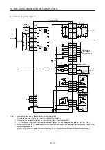
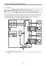
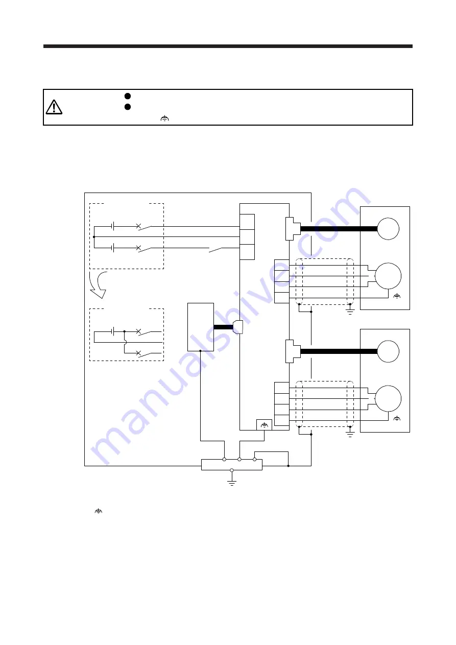
18.3.10 Grounding
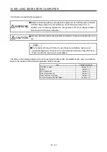
WARNING
Ground the servo amplifier and servo motor securely.
To prevent an electric shock, always connect the noiseless grounding terminal
(marked
) of the servo amplifier to the grounding terminal of the cabinet.
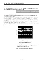
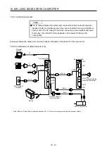
The servo amplifier switches the power transistor on-off to supply power to the servo motor. Depending on
the wiring and ground cable routing, the servo amplifier may be affected by the switching noise (due to di/dt
and dv/dt) of the transistor. To prevent such a fault, refer to the following diagram and always ground.
To conform to the EMC Directive, refer to "EMC Installation Guidelines".
W1
V1
U1
Cabinet
A-axis servo motor
M
U
V
W
CN2A
Servo amplifier
CNP1
Grounding terminal
Outer
box
24
0
PM
CNP1
(Note 2)
Encoder
W2
V2
U2
B-axis servo motor
M
U
V
W
CN2B
CNP1
(Note 2)
Circuit
protector
24 V DC
(Note 1)
48 V DC
(Note 1)
48 V DC main circuit
power supply
Circuit
protector
24 V DC
(Note 1)
24 V DC main circuit
power supply
RA
CNP1
CN3
E1
Encoder
E2
Ser
vo system
controller
Note 1. For power supply specifications, refer to section 18.1.3.
2.
Connect
of servo motor to E1 and E2 of the CNP1 connector. Do not connect the wire directly to the grounding terminal of
the cabinet.
Summary of Contents for MR-J4W2-0303B6
Page 39: ...2 INSTALLATION 2 8 MEMO ...
Page 97: ...4 STARTUP 4 20 MEMO ...
Page 181: ...6 NORMAL GAIN ADJUSTMENT 6 28 MEMO ...
Page 235: ...9 DIMENSIONS 9 6 MEMO ...
Page 245: ...10 CHARACTERISTICS 10 10 MEMO ...
Page 309: ...13 USING STO FUNCTION 13 14 MEMO ...
Page 365: ...15 USING A DIRECT DRIVE MOTOR 15 24 MEMO ...
Page 389: ...16 FULLY CLOSED LOOP SYSTEM 16 24 MEMO ...
Page 461: ...17 APPLICATION OF FUNCTIONS 17 72 MEMO ...
Page 556: ...APPENDIX App 41 ...
Page 585: ...MEMO ...

