18. MR-J4W2-0303B6 SERVO AMPLIFIER
18 - 47
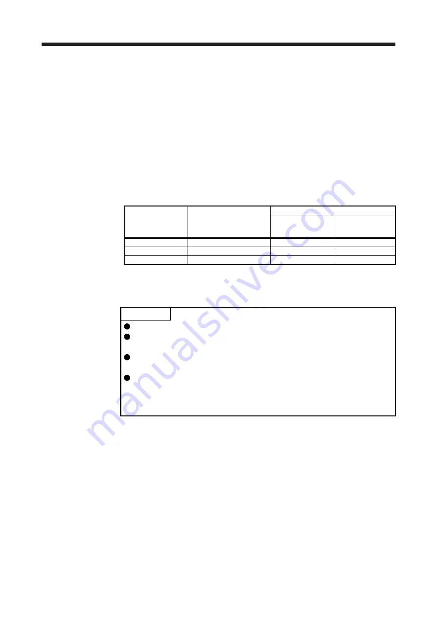
18.7.2 Power supply capacity and generated loss
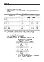
Table 18.3 indicates the required power supply capacities for main circuit and losses generated under rated
load of the servo amplifier. For thermal design of an enclosed type cabinet, use the values in the table in
consideration for the worst operating conditions. The actual amount of generated heat will be intermediate
between values at rated torque and servo-off according to the duty used during operation. When operating
the servo motor under the rated speed, required power supply capacities for main circuit will be less than the
value of the table.
The values in the table show when the same servo motors are used for both A axis and B axis. When using
different servo motors, estimate the values with an average of the two motors.
Table 18.3 Power supply capacity and generated heat per servo amplifier at
rated output
Servo motor
(×2)
Main circuit (48 V DC/24 V
DC)
Required power supply
capacity [W]
(Note) Servo amplifier-generated heat [W]
At rated output
With servo-off
HG-AK0136 460 13
3
HG-AK0236 720 19
3
HG-AK0336 960 27
3
Note. Heat generated during regeneration is not included in the servo amplifier-generated heat.
18.7.3 Dynamic brake characteristics
POINT
The dynamic brake of MR-J4W2-0303B6 is an electronic type.
Do not use dynamic brake to stop in a normal operation as it is the function to
stop in emergency.
Be sure to enable EM1 (Forced stop 1) after servo motor stops when using EM1
(Forced stop 1) frequently in other than emergency.
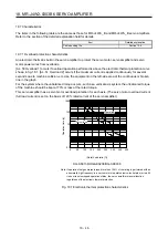
The time constant "
τ
" for the electronic dynamic brake will be shorter than that of
normal dynamic brake. Therefore, coasting distance will be longer than that of
normal dynamic brake. For how to set the electronic dynamic brake, refer to [Pr.
PF06] and [Pr. PF12].
Summary of Contents for MR-J4W2-0303B6
Page 39: ...2 INSTALLATION 2 8 MEMO ...
Page 97: ...4 STARTUP 4 20 MEMO ...
Page 181: ...6 NORMAL GAIN ADJUSTMENT 6 28 MEMO ...
Page 235: ...9 DIMENSIONS 9 6 MEMO ...
Page 245: ...10 CHARACTERISTICS 10 10 MEMO ...
Page 309: ...13 USING STO FUNCTION 13 14 MEMO ...
Page 365: ...15 USING A DIRECT DRIVE MOTOR 15 24 MEMO ...
Page 389: ...16 FULLY CLOSED LOOP SYSTEM 16 24 MEMO ...
Page 461: ...17 APPLICATION OF FUNCTIONS 17 72 MEMO ...
Page 556: ...APPENDIX App 41 ...
Page 585: ...MEMO ...


