APPENDIX
App. - 27
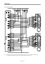
App. 5.8 Signal
App. 5.8.1 Connector/pin assignment
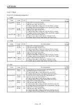
(1) CN8A
Device Symbol
Pin
No.
Function/Application
I/O
division
A-axis STO1
STO1A-
STO1A+
1
4
Outputs STO1 to A-axis driving device.
Outputs the same signal as A-axis STO2.
STO state (base shutdown): Between STO1A+ and STO1A- is opened.
STO release state (in driving): Between STO1A+ and STO1A- is closed.
O
A-axis STO2
STO2A-
STO2A+
5
6
Outputs STO2 to A-axis driving device.
Outputs the same signal as A-axis STO1.
STO state (base shutdown): Between STO2A+ and STO2A- is opened.
STO release state (in driving): Between STO2A+ and STO2A- is closed.
O
A-axis STO state
TOF2A
TOF1A
7
8
Inputs STO state of A-axis driving device.
STO state (base shutdown): Open between TOF2A and TOF1A.
STO release state (in driving): Close between TOF2A and TOF1A.
I
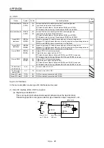
(2) CN8B
Device Symbol
Pin
No.
Function/Application
I/O
division
B-axis STO1
STO1B-
STO1B+
1
4
Outputs STO1 to B-axis driving device.
Outputs the same signal as B-axis STO2.
STO state (base shutdown): Between STO1B+ and STO1B- is opened.
STO release state (in driving): Between STO1B+ and STO1B- is closed.
O
B-axis STO2
STO2B-
STO2B+
5
6
Outputs STO2 to B-axis driving device.
Outputs the same signal as B-axis STO1.
STO state (base shutdown): Between STO2B+ and STO2B- is opened.
STO release state (in driving): Between STO2B+ and STO2B- is closed.
O
B-axis STO state
TOF2B
TOF1B
7
8
Inputs STO state of B-axis driving device.
STO state (base shutdown): Open between TOF2B and TOF1B.
STO release state (in driving): Close between TOF2B and TOF1B.
I
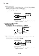
(3) CN9
Device Symbol
Pin
No.
Function/Application
I/O
division
A-axis shutdown 1 SDI1A+
SDI1A-
1A
1B
Connect this device to a safety switch for A-axis driving device.
Input the same signal as A-axis shutdown 2.
STO state (base shutdown): Open between SDI1A+ and SDI1A-.
STO release state (in driving): Close between SDI1A+ and SDI1A-.
DI-1
B-axis shutdown 1 SDI1B+
SDI1B-
2A
2B
Connect this device to a safety switch for B-axis driving device.
Input the same signal as B-axis shutdown 2.
STO state (base shutdown): Open between SDI1B+ and SDI1B-.
STO release state (in driving): Close between SDI1B+ and SDI1B-.
DI-1
A-axis SDO1
SDO1A+
SDO1A-
4A
4B
Outputs STO1 to A-axis driving device.
Outputs the same signal as A-axis SDO2.
STO state (base shutdown): Between SDO1A+ and SDO1A- is opened.
STO release state (in driving): Between SDO1A+ and SDO1A- is closed.
DO-1
B-axis SDO1
SDO1B+
SDO1B-
3A
3B
Outputs STO1 to B-axis driving device.
Outputs the same signal as B-axis SDO2.
STO state (base shutdown): Between SDO1B+ and SDO1B- is opened.
STO release state (in driving): Between SDO1B+ and SDO1B- is closed.
DO-1
Summary of Contents for MR-J4W2-0303B6
Page 39: ...2 INSTALLATION 2 8 MEMO ...
Page 97: ...4 STARTUP 4 20 MEMO ...
Page 181: ...6 NORMAL GAIN ADJUSTMENT 6 28 MEMO ...
Page 235: ...9 DIMENSIONS 9 6 MEMO ...
Page 245: ...10 CHARACTERISTICS 10 10 MEMO ...
Page 309: ...13 USING STO FUNCTION 13 14 MEMO ...
Page 365: ...15 USING A DIRECT DRIVE MOTOR 15 24 MEMO ...
Page 389: ...16 FULLY CLOSED LOOP SYSTEM 16 24 MEMO ...
Page 461: ...17 APPLICATION OF FUNCTIONS 17 72 MEMO ...
Page 556: ...APPENDIX App 41 ...
Page 585: ...MEMO ...


