4. STARTUP
4 - 12
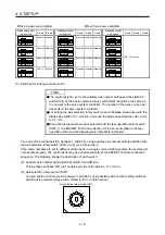
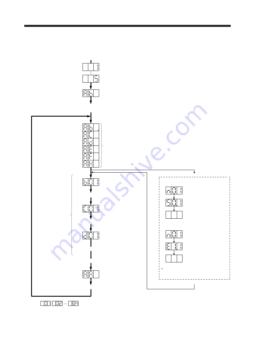
4.3.3 Status display of an axis
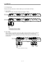
(1) Display sequence
The segment of the last 2 digits shows the axis number.
Servo system controller power on
(SSCNET III/H communication begins)
Ready-on
Servo-on
Ordinary operation
Servo system controller power off
Servo system controller power on
When alarm occurs, its
alarm code appears.
Waiting for servo system controller power to switch on
(SSCNET III/H communication)
Ready-on and servo-off
Ready-on and servo-on
(Note)
(Note)
(Note)
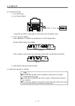
When an alarm No. or warning No. is displayed
Axis
No. 1
Axis
No. 2
Axis
No. 64
Initial data communication with the
servo system controller
(initialization communication)
Ready-off and ready-off
Note.
Example:
Blinking
Blinking
After 0.8 s
Blank
After 0.8 s
When [AL. 50 Overload 1]
occurs at axis No. 1
Example:
Blinking
Blinking
After 0.8 s
Blank
Alarm reset or warning cleared
After 0.8 s
When [AL. E1 Overload warning 1]
occurs at axis No. 1
During a warning that does not cause
servo-off, the decimal point on the third
digit LED shows the servo-on status.
Servo amplifier power on
System check in progress
Summary of Contents for MR-J4W2-0303B6
Page 39: ...2 INSTALLATION 2 8 MEMO ...
Page 97: ...4 STARTUP 4 20 MEMO ...
Page 181: ...6 NORMAL GAIN ADJUSTMENT 6 28 MEMO ...
Page 235: ...9 DIMENSIONS 9 6 MEMO ...
Page 245: ...10 CHARACTERISTICS 10 10 MEMO ...
Page 309: ...13 USING STO FUNCTION 13 14 MEMO ...
Page 365: ...15 USING A DIRECT DRIVE MOTOR 15 24 MEMO ...
Page 389: ...16 FULLY CLOSED LOOP SYSTEM 16 24 MEMO ...
Page 461: ...17 APPLICATION OF FUNCTIONS 17 72 MEMO ...
Page 556: ...APPENDIX App 41 ...
Page 585: ...MEMO ...


