Instructions and Cautions for
Safe Use of AC Servos
MR-J4W2-22B to MR-J4W2-1010B
MR-J4W3-222B and MR-J4W3-444B
MR-J4 Multi-axis Servo amplifier
General-Purpose AC Servo
C
IB(NA)0300176-C(1201)MEE
HEAD OFFICE: TOKYO BLDG MARUNOUCHI TOKYO 100-8310
Printed in Japan
This guide uses recycled paper.
Specifications subject to change without notice.
Country/Region
USA
Germany
Italy
China
Taiwan
Korea
Singapore
Sales office
Mitsubishi Electric Automation Inc.
500 Corporate Woods Parkway, Vernon Hills, IL 60061, USA
Mitsubishi Electric Europe B.V. German Branch
Gothaer Strasse 8, D-40880 Ratingen, Germany
Mitsubishi Electric Europe B.V. Italian Branch
Viale Colleoni 7
1-20041 Agrate Brianza (Milano), Italy
Mitsubishi Electric Automation (China) Ltd.
4F Zhi Fu Plazz, No. 80 Xin Chang Road
Shanghai 200003, China
Setsuyo Enterprise Co., Ltd.
6F, No.105 Wu-Kung 3rd Rd, Wu-Ku Hsiang, Taipei Hsine, Taiwan
Mitsubishi Electric Automation Korea Co., Ltd.
3F, 1480-6, Gayang-dong, Gangseo-gu, Seoul
157-200, Korea
Mitsubishi Electric Asia Pte, Ltd.
307 Alexandra Road #05-01/02,
Mitsubishi Electric Building Singapore 159943
Tel/Fax
Tel :+1-847-478-2100
Fax :+1-847-478-0327
Tel :+49-2102-486-0
Fax :+49-2102-486-1120
Tel :+39-39-60531
Fax :+39-39-6053312
Tel :+86-21-6120-0808
Fax :+86-21-6121-2444
Tel :+886-2-2299-2499
Fax :+886-2-2299-2509
Tel :+82-2-3660-9552
Fax :+82-2-3664-8372
Tel :+65-6470-2460
Fax :+65-6476-7439
AC Servo
1. INTRODUCTION
1.1 Introduction to the manuals
If this is the first time for you to use the MELSERVO-J4 Series, read the following manuals before use.
Please read them all carefully to use the MELSERVO-J4 Series safely.
Manual name
Manual No.
MELSERVO-J4W-_B Servo Amplifier Instruction Manual
SH(NA)030105
MELSERVO-J4 Servo Amplifier Instruction Manual (Troubleshooting)
SH(NA)030109
MELSERVO Servo Motor Instruction Manual (Vol.3)(Note1)
SH(NA)030113
MELSERVO Linear Servo Motor Instruction Manual (Note 2)
SH(NA)030110
MELSERVO Linear Encoder Instruction Manual (Note 2, 4)
SH(NA)030111
MELSERVO Direct Drive Motor Instruction Manual (Note 3)
SH(NA)030112
Note 1.
2.
3.
4.
It is necessary for using a rotary servo motor.
It is necessary for using a linear servo motor.
It is necessary for using a direct drive motor.
It is necessary for using a fully closed loop system (available in the future).
1.2 Contents of the packing
Unpack the product and check the rating plate to see if the servo motor is as you ordered.
Contents Quantity
Servo amplifier
1
Servo amplifier power supply connector CNP1/CNP2/CNP3A/CNP3B/CNP3C (Note)
1 each
Open tool for servo amplifier power supply connector
1
MELSERVO-J4 Series Instructions and Cautions for Safe Use of AC Servos (This installation guide)
1
Short-circuit connector CN8
1
Note. CNP3C is for MR-J4 3-axis servo amplifier.
1.3 Model code definition
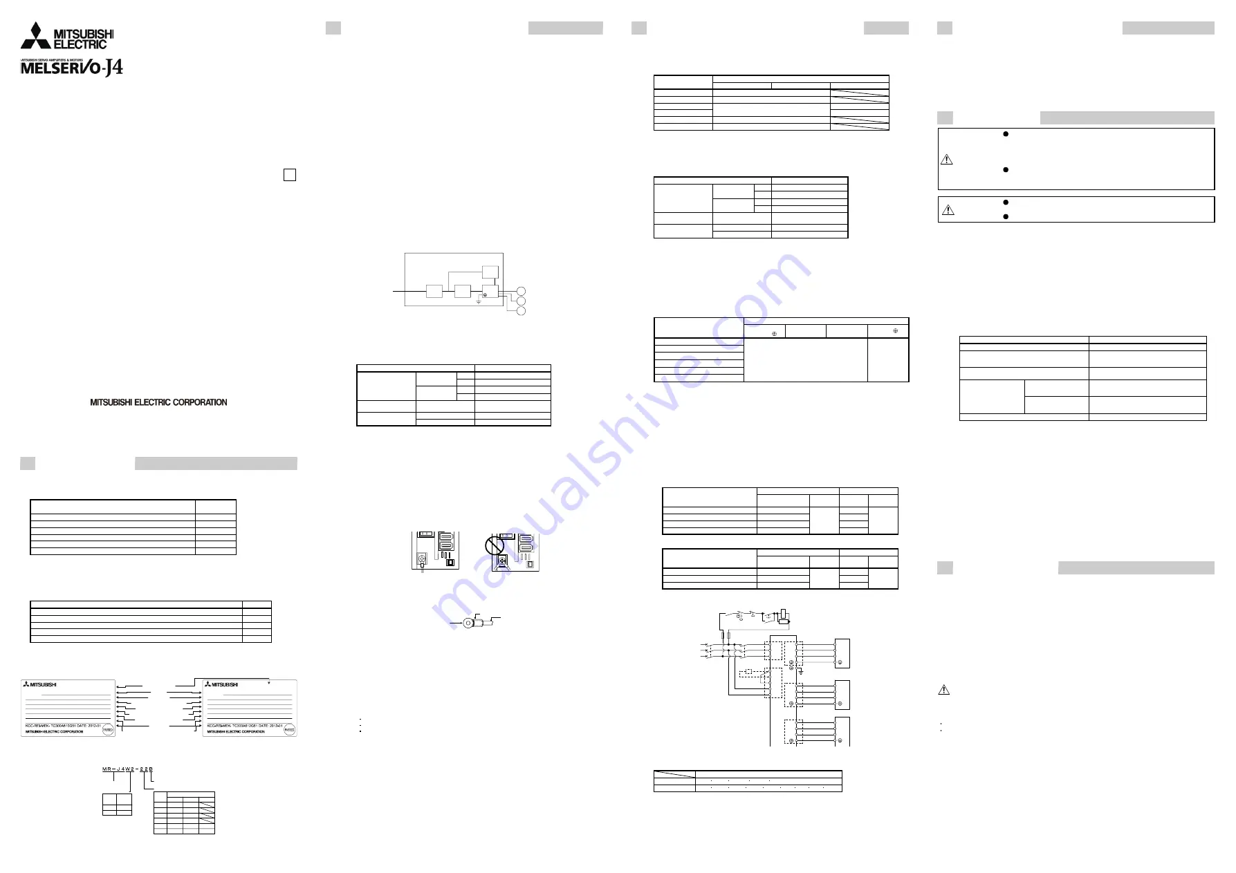
(1) Rating plate
MODEL
TOKYO 100-8310, JAPAN
MADE IN JAPAN
MR-J4W2-22B
SER. S21001001
AC SERVO
POWER
INPUT
OUTPUT
STD.: IEC/EN61800-5-1 MAN.: IB(NA)0300176
Max. Surrounding Air Temp.: 55°C
IP20
: 200W×2 (A, B)
: 3AC/AC200-240V 2.9A/5.0A 50/60Hz
: 3PH170V 0-360Hz 1.5A×2(A, B)
MODEL
TOKYO 100-8310, JAPAN
MADE IN JAPAN
MR-J4W3-222B
SER. S21001001
AC SERVO
POWER
INPUT
OUTPUT
STD.: IEC/EN61800-5-1 MAN.: IB(NA)0300176
Max. Surrounding Air Temp.: 55°C
IP20 (Except for fan finger guard)
: 200W×3 (A, B, C)
: 3AC/AC200-240V 4.3A/7.5A 50/60Hz
: 3PH170V 0-360Hz 1.5A×3(A, B, C)
Serial number
Model
Capacity
Applicable power supply
Rated output current
Standard, Manual number
Ambient temperature
IP rating
KC mark number, The year and
month of manufacture
MR-J4 2-axis servo amplifier
MR-J4 3-axis servo amplifier
(2) Model
The following describes what each block of a model name indicates. Not all combinations of the symbols are
available.
Symbol
SSCNETIII/H interface
Rated output
Number of axis
Symbol
Rated output [kW]
44
22
77
A-axis
B-axis
C-axis
0.2
0.4
0.75
1
0.2
0.4
0.2
0.4
0.75
1
0.2
0.4
0.2
0.4
222
444
1010
Series
W2
W3
Number
of axis
2
3
2. COMPLIANCE WITH CE MARKING
This servo amplifier is designed to comply with EN61800-3 and EN61800-5-1 standard.
2.1 What is CE marking?
The CE marking is mandatory and must be affixed to specific products placed on the European Union. When a
product conforms to the requirements, the CE marking must be affixed to the product. The CE marking also applies
to machines and equipment incorporating servos.
(1) EMC directive
The EMC directive applies to the servo units alone. This servo is designed to comply with the EMC directive.
The EMC directive also applies the servo-incorporated machines and equipment. This requires the EMC filters
to be used with the servo-incorporated machines and equipment to comply with the EMC directive.
(2) Low voltage directive
The low voltage directive applies also to servo units alone. This servo is designed to comply with the low
voltage directive.
(3) Machinery directive (Compliance scheduled)
The MR-J4 series servo amplifiers comply with the safety component laid down in the Machinery directive.
Do not allow using the machine until the machine in which this servo amplifier is mounted is declared to comply
with the machinery directive.
2.2 For compliance
Be sure to perform an appearance inspection of every unit before installation. In addition, have a final performance
inspection on the entire machine/system, and keep the inspection record.
(1) Servo amplifiers and servo motors used
Use servo amplifiers and servo motors which standard product.
Servo amplifier: MR-J4W2-22B, MR-J4W2-44B, MR-J4W2-77B, MR-J4W2-1010B, MR-J4W3-222B
MR-J4W3-444B
Servo motor: HG-MR_, HG-KR_, HG-SR_
(2)
Structure
To comply with the CE marking, configure each equipment as follows.
Servo motor (Note)
M
M
M
Cabinet
Molded case
circuit breaker
Magnetic
contactor
Servo
amplifier
Reinforced
insulating type
24 V DC
power
supply
MC
MCCB
Note. This shows the MR-J4 3-axis servo amplifier. Two servo motors are connected for the MR-J4 2-
axis servo amplifier.
(3) Environment
(a) Operate the servo amplifier at pollution degree 2 or 1 set forth in EN 61800-5-1. For this purpose, install the
servo amplifier in a cabinet which is protected against water, oil, carbon, dust, dirt, etc. (IP54).
(b) Use the equipment under the following environment.
Item Environment
[°C]
0 to 55 (non-freezing)
Operation
[°F]
32 to 131 (non-freezing)
(Note)
Ambient temperature
[°C]
-20 to 65 (non-freezing)
Storage,
Transportation
[°F]
-4 to 149 (non-freezing)
Ambient humidity
Operation, Storage,
Transportation
90%RH or less (non-condensing)
Operation, Storage
1000 m or less
Altitude
Transportation
10000 m or less
Note. Ambient temperature is the internal temperature of the cabinet.
(4) Power supply
(a) This servo amplifier can be supplied from star-connected supply with grounded neutral point of overvoltage
category III set forth in EN 61800-5-1. However, when using the neutral point of 400 V system for single
phase supply, a reinforced insulating transformer is required in the power input section.
(b) The control circuit provides safe separation to the main circuit in the servo amplifier. For the interface power
supply, use a 24 V DC power supply with reinforced insulation on I/O terminals.
(5) Grounding
(a) To prevent an electric shock, always connect the protective earth (PE) terminal of the CNP3 connector of
the servo amplifier for grounding. Connect the grounding lead wire from the servo motor to the protective
earth (PE) terminal of the servo amplifier terminal block, and then connect the wire from the servo amplifier
to the ground via the protective earth (PE) of the cabinet.
(b) Do not connect two ground cable to the same protective earth (PE) terminal. Always connect cables to the
terminals one-to-one.
PE terminals
PE terminals
(c) If a leakage current breaker is used, always ground the protective earth (PE) terminal of the servo amplifier
to prevent an electric shock.
(6) Wiring
(a) The wires to be connected to the terminal block of the servo amplifier must have crimping terminals
provided with insulating tubes to prevent contact with adjacent terminals.
Insulating tube
Wire
Crimping terminal
(b) Use the servo motor-side power connector which complies with EN. The EN compliant power connector
sets are available from us as options.
(c) The servo amplifier must be installed in the metal cabinet.
(7) Peripheral devices, options
(a) Use the molded case circuit breaker and magnetic contactor models which are EN Standard-compliant
products given in the MR-J4 Series Servo Amplifier Instruction Manual. Use a residual current device
(RCD) of type B as necessary. When it is not used, provide insulation between the servo amplifier and
other device by double insulation or reinforced insulation, or install a transformer between the main power
supply and the servo amplifier.
Refer to Chapter 3 (7) for the compliance with molded case circuit breaker and fuse.
(b) The sizes of the wires given in the MR-J4 Series Servo Amplifier Instruction Manual meet the following
conditions. For use in any other conditions, follow Table 6 and Annex D of EN 60204-1.
Ambient temperature: 40 °C (104 °F)
Insulator: PVC (polyvinyl chloride)
Route the wires on wall surface or open cable tray.
(c) Use shielded wires for the power wires.
(d) Use the HF3000A-UN series EMC filter manufactured by Soshin Electric.
(e) Use a RSPD-250-U4 surge protector manufactured by Okaya Electric Industries.
(8) Performing EMC tests
When EMC tests are run on a machine/device into which the servo amplifier has been installed, it must
conform to the electromagnetic compatibility (immunity/emission) standards after it has satisfied the operating
environment/electrical equipment specifications.
(9) Short circuit rating (SCCR: Short Circuit Current Rating)
We confirmed in the short-circuit test that this servo amplifier is suitable for use in a circuit rated at 100 kA
RMS or less, and maximum voltage 500 V.
(10) Configuration diagram
Refer to Chapter 3 (8) for the compliance with configuration diagram.
3. COMPLIANCE WITH UL/CSA STANDARD
For the situation of safety certification, contact your local sales office.
This servo amplifier is designed to comply with UL 508C and CSA C22.2 No.14 standard.
(1) Servo amplifiers and servo motors used
Use servo amplifiers and servo motors which standard product.
Servo
motor
Servo amplifier
HG-MR HG-KR HG-SR
MR-J4W2-22B 053/13/23
MR-J4W2-44B 053/13/23/43
MR-J4W2-77B
51/52
MR-J4W2-1010B
43/73
51/52/81/102
MR-J4W3-222B 053/13/23
MR-J4W3-444B 053/13/23/43
(2) Installation
The MR-J4 series have been approved as the products which have been installed in a cabinet. The minimum
cabinet size is based on 150% of each MR-J4 combination. And also, design the cabinet so that the ambient
temperature in the cabinet is 55 °C (131 °F) or less.
The servo amplifier must be installed in the metal cabinet.
To ensure safety, do not touch the charging section for 15 minutes after power-off.
Item Environment
[°C]
0 to 55 (non-freezing)
Operation
[°F]
32 to 131 (non-freezing)
(Note)
Ambient temperature
[°C]
-20 to 65 (non-freezing)
Storage,
Transportation
[°F]
-4 to 149 (non-freezing)
Ambient humidity
Operation, Storage,
Transportation
90%RH or less (non-condensing)
Operation, Storage
1000 m or less
Altitude
Transportation
10000 m or less
Note. Ambient temperature is the internal temperature of the cabinet.
(3) Short circuit rating (SCCR: Short Circuit Current Rating)
We confirmed in the short-circuit test that this servo amplifier is suitable for use in a circuit rated at 100 kA
RMS or less, and maximum voltage 500 V.
(4) Overload protection characteristics
Servo amplifier MR-J4W series has solid-state servo motor overload protection for each axis. (It is set on the
basis (full load current) of 120% rated current of the servo amplifier.)
(5) Selection example of wires
To comply with the UL/CSA Standard, use UL-approved copper wires rated at 75 °C (167 °F) for wiring.
Wire [AWG]
Servo amplifier
(Note 1)
L1/L2/L3/
L11/L21 P+/C/D U/V/W/
MR-J4W2-22B
MR-J4W2-44B
MR-J4W2-77B
MR-J4W2-1010B
MR-J4W3-222B
MR-J4W3-444B
14
(Note
2)
Note 1.
2.
Use the crimping terminal specified as below for the PE terminal of the servo amplifier.
Crimping terminal: FVD2-4
Tool (body): YNT-1614
Manufacturer: JST
Tightening torque: 1.2 [N•m]
The wire size depends on the servo motor characteristics.
(6) About wiring protection
For installation in United States, branch circuit protection must be provided, in accordance with the National
Electrical Code and any applicable local codes.
For installation in Canada, branch circuit protection must be provided, in accordance with the Canada Electrical
Code and any applicable provincial codes.
(7) Options, peripheral devices
Use the UL/CSA Standard-compliant products.
Use the molded case circuit breaker (UL489 Listed MCCB) or a Class T fuse indicated in the table below.
(a) MR-J4W2
Molded case circuit breaker
Fuse
Servo motor total output
Current
Voltage AC
[V]
Current [A] Voltage AC
[V]
400 W or less
50 A frame 5 A
10
From over 400 W to 900 W
50 A frame 10 A
15
From over 900 W to 1.6 kW
50 A frame 15 A
240
20
300
From over 1.6 kW to 2 kW
50 A frame 20 A
30
(b) MR-J4W3
Molded case circuit breaker
Fuse
Servo motor total output
Current
Voltage AC
[V]
Current
[A]
Voltage AC
[V]
400 W or less
50 A frame 5 A
10
From over 400 W to 900 W
50 A frame 10 A
15
300
From over 900 W to 1.2 kW
50 A frame 15 A
240
20
(8) Connection example
Servo amplifier
CNP2
P+
C
D
Regenerative
option
CNP1
U
V
W
U
V
W
Servo motor
CNP3A
U
V
W
U
V
W
Servo motor
CNP3B
U
V
W
U
V
W
Servo motor
CNP3C
Malfunction
RA1
OFF
MC
ON
M
C
SK
EMG stop
switch
L11
L21
L1
L2
L3
Power
supply
MC
MCCB
or fuse
(9) Power supply
The control circuit provides safe separation to the main circuit in the servo amplifier.
Connector/terminal
Main circuit
CNP1 CNP2 CNP3A CNP3B CNP3C
Control circuit
CN1A CN1B CN2A CN2B CN2C CN3 CN4 CN5 CN8
4. COMPLIANCE WITH KC MARK
For the situation of compliance, contact your local sales office.
Note the following when using the product in South Korea.
이
기기는
업무용
(A
급
)
전자파적합기기로서
판
매자
또는
사용자는
이
점을
주의하시기
바라며
,
가정외의
지역에서
사용하는
것을
목적으
로
합니다
.
(The product is for business use (Class A) and meets the electromagnetic compatibility
requirements. The seller and the user must note the above point, and use the product in a place
except for home.)
5. INSPECTION
WARNING
Before starting maintenance and/or inspection, turn off the power and
wait for 15 minutes or more until the charge lamp turns off. Otherwise, an
electric shock may occur. In addition, when confirming whether the
charge lamp is off or not, always confirm it from the front of the servo
amplifier.
To avoid an electric shock, only qualified personnel should attempt
inspections. For repair and parts replacement, contact your local sales
office.
CAUTION
Do not perform insulation resistance test on the servo amplifier.
Otherwise, it may cause a malfunction.
Do not disassemble and/or repair the equipment on customer side.
(1) Inspection
It is recommend that the following points periodically be checked.
(a) Check for loose terminal block screws. Retighten any loose screws.
(b) Check the cables and the like for scratches and cracks. Inspect them periodically according to operating
conditions especially when the servo motor is movable.
(c) Check that the connector is securely connected to the servo amplifier.
(d) Check that the wires are not coming out from the connector.
(e) Check for dust accumulation on the servo amplifier.
(f) Check for unusual noise generated from the servo amplifier.
(2) Parts having service lives
Service lives of the following parts are listed below. However, the service lives vary depending on operating
methods and environment. If any fault is found in the parts, they must be replaced immediately regardless of
their service lives. For parts replacement, please contact your local sales office.
Part name
Life guideline
Smoothing capacitor
10 years
Relay
Number of power-on and number of emergency stop
times: 100,000 times
Number of on and off for STO: 1,000,000 times
Cooling fan
50,000 hours to 70,000 hours
(7 years to 8 years)
Rotary servo motor
Approximately 40,000 hours/2 axes, 30,000 hours/3
axes, or 10,000 hours/8 axes (equipment power
supply: off, ambient temperature: 20 °C (68 °F))
(Note 1) Battery backup time
Direct drive motor
Approximately 10,000 hours/2 axes, 7,000 hours/3
axes, or 2,000 hours/8 axes (equipment power supply:
off, ambient temperature: 20 °C (68 °F))
(Note 2) Battery life
5 years from date of manufacture
Note 1.
2.
The data-holding time using five batteries of MR-BAT6V1 on condition that the power supply of the servo
amplifier is off. Replace the batteries within 3 years since the operation start whether the power supply of the
servo amplifier is on/off.
Quality of the batteries degrades by the storage condition. The battery life is 5 years from the production date
regardless of the connection status.
(a) Smoothing capacitor
Affected by ripple currents, etc. and deteriorates in characteristic. The life of the capacitor greatly depends
on ambient temperature and operating conditions. The capacitor will reach the end of its life in 10 years of
continuous operation in normal air-conditioned environment (40 °C (104 °F) surrounding air temperature or
less).
(b) Relays
Contact faults will occur due to contact wear arisen from switching currents. Relays reach the end of their
lives when the power is turned on and emergency stop occurs 100,000 times in total, or when the STO has
been turned on and off 1,000,000 times while the servo motor is stopped under servo-off state. However,
the lives of relays may depend on the power supply capacity.
(c) Servo amplifier cooling fan
The cooling fan bearings reach the end of their life in 50,000 hours to 70,000 hours. Normally, therefore,
the cooling fan must be changed in seven or eight years of continuous operation as a guideline. It must also
be changed if unusual noise or vibration is found during inspection.
The life indicates under the yearly average ambient temperature of 40 °C (104 °F), free from corrosive gas,
flammable gas, oil mist, dust and dirt.
6. ALARM/WARNING
For details on each type of alarms or warnings, refer to MELSERVO-J4 Servo Amplifier Instruction Manual
(Troubleshooting).
●
DISPOSAL OF WASTE
●
Please dispose a servo amplifier, battery (primary battery) and other options according to your local
laws and regulations.
Battery transportation
To transport lithium batteries, take actions to comply with the instructions and regulations such as
the United Nations (UN), the International Civil Aviation Organization (ICAO), and the International
Maritime Organization (IMO).
EEP-ROM life
The number of write times to the EEP-ROM, which stores parameter settings, etc., is limited to
100,000. If the total number of the following operations exceeds 100,000, the servo amplifier may
malfunction when the EEP-ROM reaches the end of its useful life.
Write to the EEP-ROM due to parameter setting changes
Write to the EEP-ROM due to device changes


