5. PARAMETERS
5 - 25
No.
Symbol
Name and function
Initial
value
[unit]
Setting
range
Each/
Common
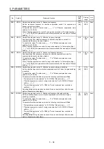
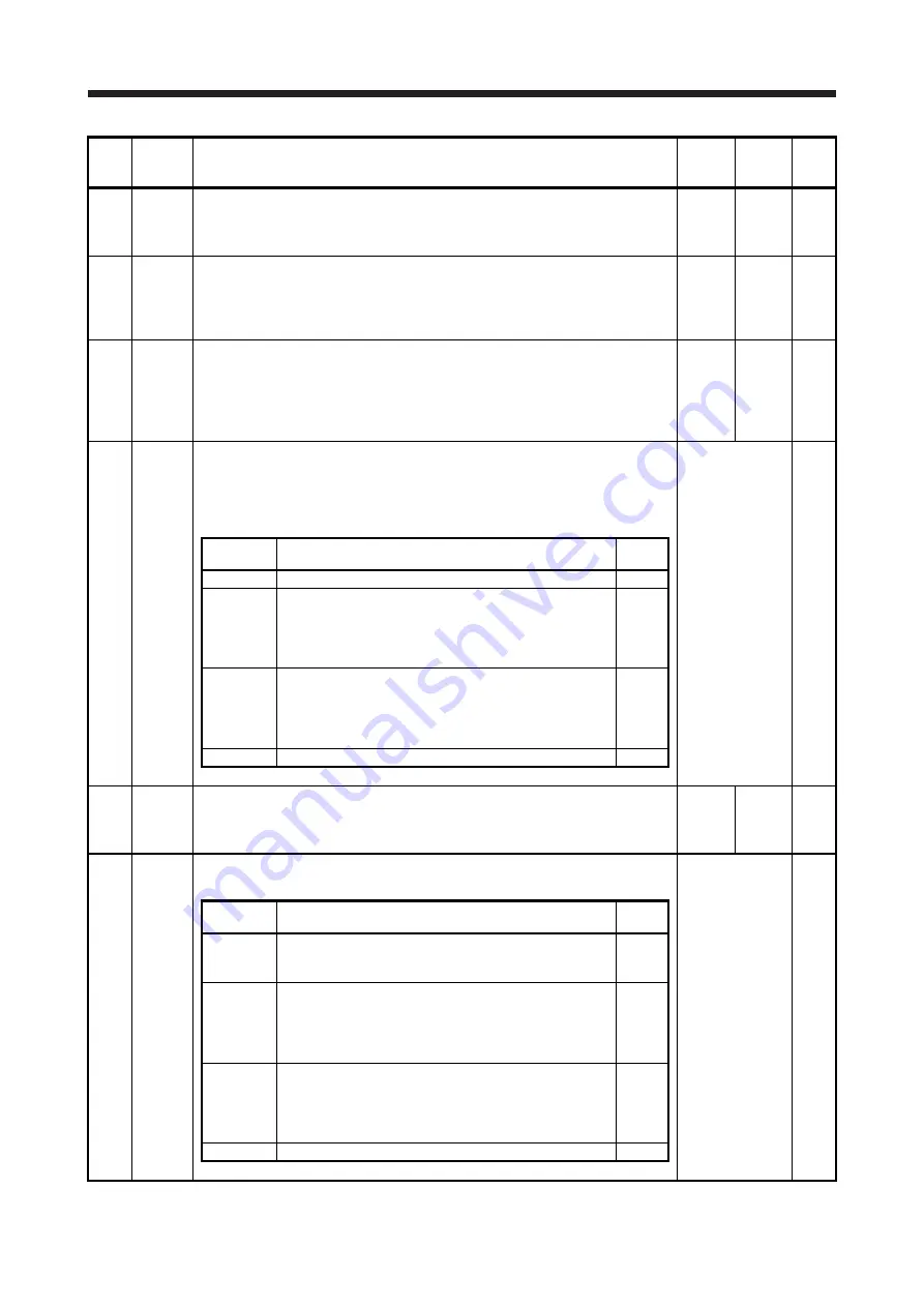
PB11
VDC
Speed differential compensation
Set a differential compensation.
To enable the parameter, select "Continuous PID control enabled (_ _ 3 _)" of "PI-PID
switching control selection" in [Pr. PB24].
980
0 to
1000
Each
PB12
OVA
Overshoot amount compensation
Set a viscous friction torque or thrust to rated torque in percentage unit at servo motor
rated speed or linear servo motor rated speed.
When the response level is low or when the torque/thrust is limited, the efficiency of
the parameter may be lower.
0
[%]
0 to
100
Each
PB13
NH1
Machine resonance suppression filter 1
Set the notch frequency of the machine resonance suppression filter 1.
When you select "Automatic setting (_ _ _ 1)" of "Filter tuning mode selection" in [Pr.
PB01], this parameter will be adjusted automatically.
When you select "Manual setting (_ _ _ 2)" of "Filter tuning mode selection" in [Pr.
PB01], the setting value will be enabled.
4500
[Hz]
10 to
4500
Each
PB14
NHQ1
Notch shape selection 1
Set the shape of the machine resonance suppression filter 1.
When you select "Automatic setting (_ _ _ 1)" of "Filter tuning mode selection" in [Pr.
PB01], this parameter will be adjusted automatically.
Set manually for the manual setting.
Refer to Name
and function
column.
Each
Setting
digit
Explanation
Initial
value
_ _ _ x
For manufacturer setting
0h
_ _ x _
Notch depth selection
0: -40 dB
1: -14 dB
2: -8 dB
3: -4 dB
0h
_ x _ _
Notch width selection
0:
α
= 2
1:
α
= 3
2:
α
= 4
3:
α
= 5
0h
x _ _ _
For manufacturer setting
0h
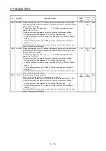
PB15
NH2
Machine resonance suppression filter 2
Set the notch frequency of the machine resonance suppression filter 2.
To enable the setting value, select "Enabled (_ _ _ 1)" of "Machine resonance
suppression filter 2 selection" in [Pr. PB16].
4500
[Hz]
10 to
4500
Each
PB16
NHQ2
Notch shape selection 2
Set the shape of the machine resonance suppression filter 2.
Refer to Name
and function
column.
Each
Setting
digit
Explanation
Initial
value
_ _ _ x
Machine resonance suppression filter 2 selection
0: Disabled
1: Enabled
0h
_ _ x _
Notch depth selection
0: -40 dB
1: -14 dB
2: -8 dB
3: -4 dB
0h
_ x _ _
Notch width selection
0:
α
= 2
1:
α
= 3
2:
α
= 4
3:
α
= 5
0h
x _ _ _
For manufacturer setting
0h
Summary of Contents for MR-J4W2
Page 9: ...A 8 MEMO ...
Page 17: ...8 MEMO ...
Page 31: ...1 FUNCTIONS AND CONFIGURATION 1 14 MEMO ...
Page 95: ...4 STARTUP 4 20 MEMO ...
Page 169: ...6 NORMAL GAIN ADJUSTMENT 6 20 MEMO ...
Page 201: ...7 SPECIAL ADJUSTMENT FUNCTIONS 7 32 MEMO ...
Page 213: ...8 TROUBLESHOOTING 8 12 MEMO ...
Page 219: ...9 OUTLINE DRAWINGS 9 6 MEMO ...
Page 229: ...10 CHARACTERISTICS 10 10 MEMO ...
Page 295: ...13 USING STO FUNCTION 13 14 MEMO ...
Page 327: ...14 USING A LINEAR SERVO MOTOR 14 32 MEMO ...
Page 371: ...16 FULLY CLOSED LOOP SYSTEM 16 24 MEMO ...
Page 521: ...APPENDIX App 38 ...
Page 537: ...MEMO ...
Page 541: ......


