5. PARAMETERS
5 - 37
No.
Symbol
Name and function
Initial
value
[unit]
Setting
range
Each/
Common
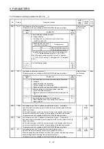
PC04 **COP1 Function selection C-1
Select the encoder cable communication method selection.
Refer to Name
and function
column.
Each
Setting
digit
Explanation
Initial
value
_ _ _ x
For manufacturer setting
0h
_ _ x _
0h
_ x _ _
0h
x _ _ _
Encoder cable communication method selection
0: Two-wire type
1: Four-wire type
Incorrect setting will result in [AL. 16 Encoder initial
communication error 1]. Or [AL. 20 Encoder initial
communication error 1] will occur. Setting "1" will trigger
[AL. 37] while "Fully closed loop control mode (_ _ 1 _)" is
selected in [Pr. PA01].
For MR-J4W2-0303B6 servo amplifiers, this digit cannot be
used other than the initial value.
0h
PC05 **COP2 Function selection C-2
Set the motor-less operation, servo motor main circuit power supply, and [AL. 9B Error
excessive warning].
Refer to Name
and function
column.
Each
Setting
digit
Explanation
Initial
value
_ _ _ x
Motor-less operation selection
0: Disabled
1: Enabled
0h
_ _ x _
For manufacturer setting
0h
_ x _ _
Main circuit power supply selection
Select a voltage to be connected to the main circuit power
supply with an MR-J4W2-0303B6 servo amplifier.
0: 48 V DC
1: 24 V DC
When using 24 V DC for the main circuit power supply, set
"1" to this digit.
The setting of this digit in the J3 compatibility mode is the
same as the MR-J3W-0303BN6 servo amplifier. Set it with
[Pr. Po04]. For details, refer to "MR-J3W-0303BN6 MR-
J3W-_B Servo Amplifier Instruction Manual".
This digit is not available with MR-J4W_-_B 200 W or more
servo amplifiers.
The characteristics of the servo motor vary depending on
whether 48 V DC or 24 V DC is used. For details, refer to
"Servo Motor Instruction Manual (Vol. 3)".
0h
x _ _ _
[AL. 9B Error excessive warning] selection
0: [AL. 9B Error excessive warning] is disabled.
1: [AL. 9B Error excessive warning] is enabled.
The setting of this digit is used by servo amplifier with
software version B4 or later.
0h
Summary of Contents for MR-J4W2
Page 9: ...A 8 MEMO ...
Page 17: ...8 MEMO ...
Page 31: ...1 FUNCTIONS AND CONFIGURATION 1 14 MEMO ...
Page 95: ...4 STARTUP 4 20 MEMO ...
Page 169: ...6 NORMAL GAIN ADJUSTMENT 6 20 MEMO ...
Page 201: ...7 SPECIAL ADJUSTMENT FUNCTIONS 7 32 MEMO ...
Page 213: ...8 TROUBLESHOOTING 8 12 MEMO ...
Page 219: ...9 OUTLINE DRAWINGS 9 6 MEMO ...
Page 229: ...10 CHARACTERISTICS 10 10 MEMO ...
Page 295: ...13 USING STO FUNCTION 13 14 MEMO ...
Page 327: ...14 USING A LINEAR SERVO MOTOR 14 32 MEMO ...
Page 371: ...16 FULLY CLOSED LOOP SYSTEM 16 24 MEMO ...
Page 521: ...APPENDIX App 38 ...
Page 537: ...MEMO ...
Page 541: ......


