7. SPECIAL ADJUSTMENT FUNCTIONS
7 - 28
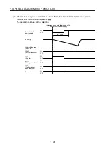
(b) When the bus voltage does not decrease lower than 158 V DC within the instantaneous power
failure time of the control circuit power supply
The operation continues without alarming.
Control circuit
power supply
Bus voltage
Undervoltage level
(158 V DC)
CALM
(AND malfunction)
MTTR
(During tough drive)
MBR
(Electromagnetic
brake interlock)
Base circuit
WNG
(Warning)
[Pr. PF25]
Instantaneous power failure time of the
control circuit power supply
ON
OFF
ON
OFF
ON
OFF
ON
OFF
ON
OFF
ON
OFF
Summary of Contents for MR-J4W2
Page 9: ...A 8 MEMO ...
Page 17: ...8 MEMO ...
Page 31: ...1 FUNCTIONS AND CONFIGURATION 1 14 MEMO ...
Page 95: ...4 STARTUP 4 20 MEMO ...
Page 169: ...6 NORMAL GAIN ADJUSTMENT 6 20 MEMO ...
Page 201: ...7 SPECIAL ADJUSTMENT FUNCTIONS 7 32 MEMO ...
Page 213: ...8 TROUBLESHOOTING 8 12 MEMO ...
Page 219: ...9 OUTLINE DRAWINGS 9 6 MEMO ...
Page 229: ...10 CHARACTERISTICS 10 10 MEMO ...
Page 295: ...13 USING STO FUNCTION 13 14 MEMO ...
Page 327: ...14 USING A LINEAR SERVO MOTOR 14 32 MEMO ...
Page 371: ...16 FULLY CLOSED LOOP SYSTEM 16 24 MEMO ...
Page 521: ...APPENDIX App 38 ...
Page 537: ...MEMO ...
Page 541: ......


