1. FUNCTIONS AND CONFIGURATION
1 - 6
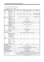
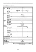
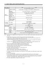
1.3.2 Integrated 3-axis servo amplifier
Model MR-J4W3-
222B
444B
Output
Rated voltage
3-phase 170 V AC
Rated current
(each axis)
[A]
1.5 2.8
Main circuit
power supply
input
Power supply
/Frequency
3-phase or 1-phase 200 V AC to 240 V AC, 50 Hz/60 Hz
Rated current
(Note 9)
[A]
4.3 7.8
Permissible voltage
fluctuation
3-phase or 1-phase 170 V AC to 264 V AC, 50 Hz/60 Hz
Permissible
frequency fluctuation
Within ±5%
Power supply
capacity [kVA]
Refer to section 10.2.
Inrush current
[A]
Refer to section 10.5.
Power supply
/Frequency
1-phase 200 V AC to 240 V AC, 50 Hz/60 Hz
Rated
current
[A]
0.4
Control circuit
power supply
input
Permissible voltage
fluctuation
1-phase 170 V AC to 264 V AC
Permissible
frequency fluctuation
Within ±5%
Power consumption
[W]
55
Inrush current
[A]
Refer to section 10.5.
Interface
power supply
Voltage/Frequency
24 V DC ± 10%
Power supply
capacity
0.45 A (Note 1)
Control method
Sine-wave PWM control, current control method
Capacitor
regeneration
Reusable regenerative
energy (Note 2)
[J]
21 30
Moment of inertia J
equivalent to the
permissible charging
amount (Note 3)
[× 10
-4
kg • m
2
]
4.26 6.08
Mass
equivalent to
the
permissible
charging
amount
(Note 4) [kg]
LM-H3 4.7
6.7
LM-K2
LM-U2
10.5 15.0
Built-in regenerative resistance
[W]
30
100
Dynamic brake
Built-in
SSCNET III/H command
communication cycle (Note 7)
0.222 ms (Note 8), 0.444 ms, 0.888 ms
Communication function
USB: Connect a personal computer (MR Configurator2 compatible)
Encoder output pulse
Not compatible
Analog monitor
None
Fully closed loop control
Not compatible
Scale measurement function
Not compatible
Protective functions
Overcurrent shut-off, regenerative overvoltage shut-off, overload shut-off (electronic thermal),
servo motor overheat protection, encoder error protection, regenerative error protection,
undervoltage protection, instantaneous power failure protection, overspeed protection, and
error excessive protection
Summary of Contents for MR-J4W2
Page 9: ...A 8 MEMO ...
Page 17: ...8 MEMO ...
Page 31: ...1 FUNCTIONS AND CONFIGURATION 1 14 MEMO ...
Page 95: ...4 STARTUP 4 20 MEMO ...
Page 169: ...6 NORMAL GAIN ADJUSTMENT 6 20 MEMO ...
Page 201: ...7 SPECIAL ADJUSTMENT FUNCTIONS 7 32 MEMO ...
Page 213: ...8 TROUBLESHOOTING 8 12 MEMO ...
Page 219: ...9 OUTLINE DRAWINGS 9 6 MEMO ...
Page 229: ...10 CHARACTERISTICS 10 10 MEMO ...
Page 295: ...13 USING STO FUNCTION 13 14 MEMO ...
Page 327: ...14 USING A LINEAR SERVO MOTOR 14 32 MEMO ...
Page 371: ...16 FULLY CLOSED LOOP SYSTEM 16 24 MEMO ...
Page 521: ...APPENDIX App 38 ...
Page 537: ...MEMO ...
Page 541: ......


