18. MR-J4W2-0303B6 SERVO AMPLIFIER
18 - 36
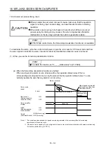
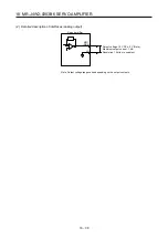
(2) When you do not use the forced stop deceleration function
POINT
To disable the function, set "0 _ _ _" in [Pr. PA04].
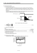
The timing chart that shows the servo motor condition when an alarm or SSCNETIII/H communication shut-
off occurs is the same as (1) (b) of this section.
18.3.9 Interfaces
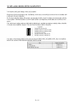
The items in the following table are the same as those for MR-J4W2-_B and MR-J4W3-_B servo amplifiers.
Refer to the section of the detailed explanation field for details.
Item Detailed
explanation
Detailed description of interfaces (excluding analog
output)
Section 3.8.2
Source I/O interface
Section 3.8.3
Summary of Contents for MR-J4W2
Page 9: ...A 8 MEMO ...
Page 17: ...8 MEMO ...
Page 31: ...1 FUNCTIONS AND CONFIGURATION 1 14 MEMO ...
Page 95: ...4 STARTUP 4 20 MEMO ...
Page 169: ...6 NORMAL GAIN ADJUSTMENT 6 20 MEMO ...
Page 201: ...7 SPECIAL ADJUSTMENT FUNCTIONS 7 32 MEMO ...
Page 213: ...8 TROUBLESHOOTING 8 12 MEMO ...
Page 219: ...9 OUTLINE DRAWINGS 9 6 MEMO ...
Page 229: ...10 CHARACTERISTICS 10 10 MEMO ...
Page 295: ...13 USING STO FUNCTION 13 14 MEMO ...
Page 327: ...14 USING A LINEAR SERVO MOTOR 14 32 MEMO ...
Page 371: ...16 FULLY CLOSED LOOP SYSTEM 16 24 MEMO ...
Page 521: ...APPENDIX App 38 ...
Page 537: ...MEMO ...
Page 541: ......


