18. MR-J4W2-0303B6 SERVO AMPLIFIER
18 - 42
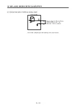
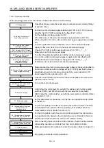
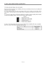
18.4.2 Troubleshooting when "24V ERROR" lamp turns on
(1) When overvoltage is applied to the control circuit in the servo amplifier, power supply to the circuit will be
shut off and the "24V ERROR" lamp will turn on. Then, the 3-digit, 7-segment LED on display will turn
off. Immediately turn off the power and check the wiring, etc. to the main circuit power supply (48 V DC).
(2) If the "24V ERROR" lamp turns on with the 3-digit, 7-segment LED on, the control circuit power supply
voltage (24 V DC) may be failure. Check that the voltage of the control circuit power supply is 21.6 V DC
or more.
18.4.3 Wiring check
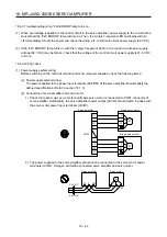
(1) Power supply system wiring
Before switching on the main circuit and control circuit power supplies, check the following items.
(a) Power supply system wiring
The power supplied to the power input terminals (24/0/PM) of the servo amplifier should satisfy the
defined specifications. (Refer to section 18.1.3)
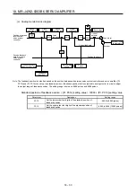
(b) Connection of servo amplifier and servo motor
1) Check that each A axis servo motor and B axis servo motor is connected to CNP1 connector of
servo amplifier. Additionally, the servo amplifier power output (U/V/W) should match in phase with
the servo motor power input terminals (U/V/W).
Servo amplifier
CNP1
A-axis servo motor
U
V
W
M
B-axis servo motor
U
V
W
M
U1
V1
W1
U2
V2
W2
E1
E2
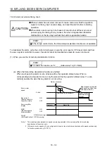
2) The power supplied to the servo amplifier should not be connected to the servo motor power
terminals (U/V/W). Doing so will fail the connected servo amplifier and servo motor.
Servo amplifier
Servo motor
24
0 PM
U
V
W
M
24 V DC
48 V DC
Summary of Contents for MR-J4W2
Page 9: ...A 8 MEMO ...
Page 17: ...8 MEMO ...
Page 31: ...1 FUNCTIONS AND CONFIGURATION 1 14 MEMO ...
Page 95: ...4 STARTUP 4 20 MEMO ...
Page 169: ...6 NORMAL GAIN ADJUSTMENT 6 20 MEMO ...
Page 201: ...7 SPECIAL ADJUSTMENT FUNCTIONS 7 32 MEMO ...
Page 213: ...8 TROUBLESHOOTING 8 12 MEMO ...
Page 219: ...9 OUTLINE DRAWINGS 9 6 MEMO ...
Page 229: ...10 CHARACTERISTICS 10 10 MEMO ...
Page 295: ...13 USING STO FUNCTION 13 14 MEMO ...
Page 327: ...14 USING A LINEAR SERVO MOTOR 14 32 MEMO ...
Page 371: ...16 FULLY CLOSED LOOP SYSTEM 16 24 MEMO ...
Page 521: ...APPENDIX App 38 ...
Page 537: ...MEMO ...
Page 541: ......


