APPENDIX
App. - 16
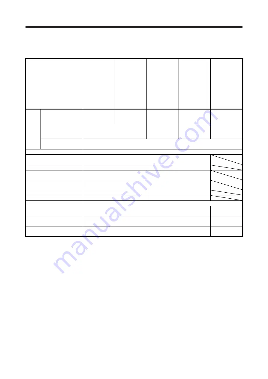
App. 4.8 Technical data
App. 4.8.1 MR-J4 servo amplifier
Item
MR-J4-10_/
MR-J4-20_/
MR-J4-40_/
MR-J4-60_/
MR-J4-70_/
MR-J4W2-22B/
MR-J4W2-44B/
MR-J4W2-77B/
MR-J4W3-222B/
MR-J4W3-444B
MR-J4-100_/
MR-J4-200_/
MR-J4-350_/
MR-J4-500_/
MR-J4-700_/
MR-J4W2-1010B/
MR-J4-11K_/
MR-J4-15K_/
MR-J4-22K_
MR-J4-10_1/
MR-J4-20_1/
MR-J4-40_1
MR-J4-60_4/
MR-J4-100_4/
MR-J4-200_4/
MR-J4-350_4/
MR-J4-500_4/
MR-J4-700_4/
MR-J4-11K_4/
MR-J4-15K_4/
MR-J4-22K_4
MR-J4-03A6/
MR-J4W2-
0303B6
Power
supply
Main circuit
(line voltage)
3-phase or 1-phase
200 V AC to 240 V
AC, 50 Hz/60 Hz
3-phase
200 V AC to 240 V
AC, 50 Hz/60 Hz
1-phase
100 V AC to 120 V
AC, 50 Hz/60 Hz
3-phase
380 V AC to 480 V
AC, 50 Hz/60 Hz
48 V DC or
24 V DC
Control circuit
(line voltage)
1-phase 200 V AC to 240 V AC,
50/60 Hz
1-phase
100 V AC to 120 V
AC, 50 Hz/60 Hz
1-phase
380 V AC to 480 V
AC, 50 Hz/60 Hz
24 V DC
Interface (SELV)
24 V DC, (required current capacity: MR-J4-_A_, 500 mA; MR-J4-_B_, 300 mA; MR-J4W2-_B_,
350 mA; MR-J4W3-_B, 450 mA)
Control method
Sine-wave PWM control, current control method
Safety observation function (STO)
IEC/EN 61800-5-2
EN ISO 13849-1 category 3 PL d, IEC 61508 SIL 2,
EN 62061 SIL CL 2, and EN 61800-5-2 SIL 2
Mean time to dangerous failure
MTTFd
≥
100 [years]
Effectiveness of fault monitoring
of a system or subsystem
DC = 90 [%]
Average probability of dangerous
failures per hour
PFH = 1.68 × 10
-10
[1/h]
Mission time
T
M
= 20 [years]
Response performance
8 ms or less (STO input off
→
energy shut off)
Pollution degree
2 (IEC/EN 60664-1)
Overvoltage category
1-phase 100 V AC/200 V AC: II (IEC/EN 60664-1),
3-phase 200 V AC/400 V AC: III (IEC/EN 60664-1)
II
(IEC/EN 60664-1)
Protective class
I (IEC/EN 61800-5-1)
III (IEC/
EN 61800-5-1)
Short-circuit current rating
(SCCR)
100 kA
5 kA (Note)
Note. For the use in US/Canada, constitute a branch circuit including the power supply which endures SCCR of 5 kA minimum in the
industrial cabinet.
Summary of Contents for MR-J4W2
Page 9: ...A 8 MEMO ...
Page 17: ...8 MEMO ...
Page 31: ...1 FUNCTIONS AND CONFIGURATION 1 14 MEMO ...
Page 95: ...4 STARTUP 4 20 MEMO ...
Page 169: ...6 NORMAL GAIN ADJUSTMENT 6 20 MEMO ...
Page 201: ...7 SPECIAL ADJUSTMENT FUNCTIONS 7 32 MEMO ...
Page 213: ...8 TROUBLESHOOTING 8 12 MEMO ...
Page 219: ...9 OUTLINE DRAWINGS 9 6 MEMO ...
Page 229: ...10 CHARACTERISTICS 10 10 MEMO ...
Page 295: ...13 USING STO FUNCTION 13 14 MEMO ...
Page 327: ...14 USING A LINEAR SERVO MOTOR 14 32 MEMO ...
Page 371: ...16 FULLY CLOSED LOOP SYSTEM 16 24 MEMO ...
Page 521: ...APPENDIX App 38 ...
Page 537: ...MEMO ...
Page 541: ......


