4. STARTUP
4 - 29
4.5.7 External I/O signal display
POINT
The I/O signal settings can be changed using the I/O setting parameters [Pr.
PD03] to [Pr. PD28].
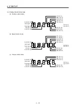
The on/off states of the digital I/O signals connected to the servo amplifier can be confirmed.
(1) Operation
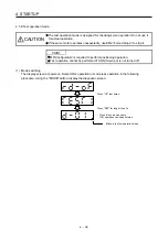
The display screen at power-on. Using the "MODE" button, display the diagnostic screen.
Press "UP" twice.
…… External I/O signal display screen
(2) Display definition
The 7-segment LED segments and CN1 connector pins correspond as shown below.
Input signals
Output signals
Always lit
CN1-
42
CN1-
41
CN1-
48
CN1-
19
CN1-
15
CN1-
23
CN1-
49
CN1-
24
Light on: on
Light off: off
CN1-
33
CN1-
44
CN1-
43
CN1-35 (Note 1)/
CN1-38 (Note 2)
CN1-10 (Note 1)/
CN1-37 (Note 2)
Note 1. This is available with servo amplifiers with software version B7 or later.
2. This is available with servo amplifiers having software version B7 or later, and manufactured in May 2015 or later.
The LED segment corresponding to the pin is lit to indicate on, and is extinguished to indicate off.
The signals corresponding to the pins in the respective control modes are indicated below.
Summary of Contents for MR-JE-_A
Page 9: ...A 8 MEMO ...
Page 15: ...6 MEMO ...
Page 29: ...1 FUNCTIONS AND CONFIGURATION 1 14 MEMO ...
Page 139: ...4 STARTUP 4 38 MEMO ...
Page 187: ...5 PARAMETERS 5 48 MEMO ...
Page 221: ...6 NORMAL GAIN ADJUSTMENT 6 34 MEMO ...
Page 259: ...8 TROUBLESHOOTING 8 8 MEMO ...
Page 265: ...9 DIMENSIONS 9 6 MEMO ...
Page 273: ...10 CHARACTERISTICS 10 8 MEMO ...
Page 339: ...12 COMMUNICATION FUNCTION MITSUBISHI ELECTRIC GENERAL PURPOSE AC SERVO PROTOCOL 12 34 MEMO ...

