7. SPECIAL ADJUSTMENT FUNCTIONS
7 - 19
Parameter Symbol
Name
Setting
value
Unit
PB28
CDT
Gain switching time constant
100
[ms]
PB33
VRF1B Vibration suppression control 1 - Vibration frequency after gain
switching
60 [Hz]
PB34
VRF2B Vibration suppression control 1 - Resonance frequency after gain
switching
60 [Hz]
PB35
VRF3B Vibration suppression control 1 - Vibration frequency damping after
gain switching
0.15
PB36
VRF4B Vibration suppression control 1 - Resonance frequency damping
after gain switching
0.15
PB56
VRF21B Vibration suppression control 2 - Vibration frequency after gain
switching
30 [Hz]
PB57
VRF22B Vibration suppression control 2 - Resonance frequency after gain
switching
30 [Hz]
PB58
VRF23B Vibration suppression control 2 - Vibration frequency damping after
gain switching
0.05
PB59 VRF24B
Vibration
suppression
control 2 - Resonance frequency damping
after gain switching
0.05
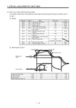
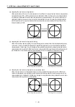
(b) Switching timing chart
After-switching gain
63.4%
CDT = 100 ms
Before-switching gain
Gain switching
CDP (gain switching)
OFF
ON
OFF
Model loop gain
100
→
50
→
100
Load to motor inertia ratio
4.00
→
10.00
→
4.00
Position loop gain
120
→
84
→
120
Speed loop gain
3000
→
4000
→
3000
Speed integral compensation
20
→
50
→
20
Vibration suppression control 1 - Vibration
frequency
50
→
60
→
50
Vibration suppression control 1 -
Resonance frequency
50
→
60
→
50
Vibration suppression control 1 - Vibration
frequency damping
0.20
→
0.15
→
0.20
Vibration suppression control 1 -
Resonance frequency damping
0.20
→
0.15
→
0.20
Vibration suppression control 2 - Vibration
frequency
20
→
30
→
20
Vibration suppression control 2 -
Resonance frequency
20
→
30
→
20
Vibration suppression control 2 - Vibration
frequency damping
0.10
→
0.05
→
0.10
Vibration suppression control 2 -
Resonance frequency damping
0.10
→
0.05
→
0.10
Summary of Contents for MR-JE-_A
Page 9: ...A 8 MEMO ...
Page 15: ...6 MEMO ...
Page 29: ...1 FUNCTIONS AND CONFIGURATION 1 14 MEMO ...
Page 139: ...4 STARTUP 4 38 MEMO ...
Page 187: ...5 PARAMETERS 5 48 MEMO ...
Page 221: ...6 NORMAL GAIN ADJUSTMENT 6 34 MEMO ...
Page 259: ...8 TROUBLESHOOTING 8 8 MEMO ...
Page 265: ...9 DIMENSIONS 9 6 MEMO ...
Page 273: ...10 CHARACTERISTICS 10 8 MEMO ...
Page 339: ...12 COMMUNICATION FUNCTION MITSUBISHI ELECTRIC GENERAL PURPOSE AC SERVO PROTOCOL 12 34 MEMO ...


