3. SIGNALS AND WIRING
3 - 27
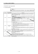
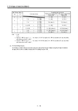
Device Symbol
Connector
pin No.
Function and application
I/O
division
Control
mode
P S T
Control switching
LOP
«Position/speed control switching mode»
This is used to select the control mode in the position/speed control
switching mode.
DI-1
Refer to
Function
and
application.
(Note)
LOP
Control
mode
0
Position
1
Speed
Note. 0: Off
1: On
«Speed/torque control switch mode»
This is used to select the control mode in the speed/torque control
switching mode.
(Note)
LOP
Control
mode
0
Speed
1
Torque
Note. 0: Off
1: On
«Torque/position control switch mode»
This is used to select the control mode in the torque/position control
switching mode.
(Note)
LOP
Control
mode
0
Torque
1
Position
Note. 0: Off
1: On
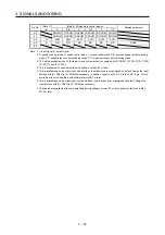
Second
acceleration/
deceleration
selection
STAB2 The device allows selection of the acceleration/deceleration time constants
at servo motor rotation in the speed control mode or torque control mode.
The s-pattern acceleration/deceleration time constant is always uniform.
DI-1
(Note)
STAB2
Acceleration/deceleration time
constant
0
Pr. PC01 Acceleration time
constant
Pr. PC02 Deceleration time
constant
1
Pr. PC30 Acceleration time
constant 2
Pr. PC31 Deceleration time
constant 2
Note. 0: Off
1: On
Summary of Contents for MR-JE-_A
Page 9: ...A 8 MEMO ...
Page 15: ...6 MEMO ...
Page 29: ...1 FUNCTIONS AND CONFIGURATION 1 14 MEMO ...
Page 139: ...4 STARTUP 4 38 MEMO ...
Page 187: ...5 PARAMETERS 5 48 MEMO ...
Page 221: ...6 NORMAL GAIN ADJUSTMENT 6 34 MEMO ...
Page 259: ...8 TROUBLESHOOTING 8 8 MEMO ...
Page 265: ...9 DIMENSIONS 9 6 MEMO ...
Page 273: ...10 CHARACTERISTICS 10 8 MEMO ...
Page 339: ...12 COMMUNICATION FUNCTION MITSUBISHI ELECTRIC GENERAL PURPOSE AC SERVO PROTOCOL 12 34 MEMO ...


