3. SIGNALS AND WIRING
3 - 37
3.6.2 Speed control mode
(1) Speed setting
(a) Speed command and speed
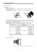
The servo motor is run at the speeds set in the parameters or at the speed set in the applied voltage
of VC (Analog speed command). A relation between VC (Analog speed command) applied voltage
and the servo motor speed is as follows.
Rated speed is achieved at ±10 V with initial setting. The speed at ±10 V can be changed with [Pr.
PC12].
Speed
[r/min]
CW
direction
Rated speed [r/min]
Rated speed [r/min]
0
CCW direction
+10
-10
VC applied voltage [V]
Forward rotation
(CCW)
Reverse rotation
(CW)
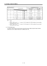
The following table indicates the rotation direction according to ST1 (Forward rotation start) and ST2
(Reverse rotation start) combination.
(Note 1) Input device
(Note 2) Rotation direction
ST2 ST1
VC (Analog speed command)
Internal speed command
Polarity: +
0 V
Polarity: -
0 0
Stop
(servo-lock)
Stop
(servo-lock)
Stop
(servo-lock)
Stop
(servo-lock)
0 1
CCW
Stop
(no servo-lock)
CW CCW
1 0
CW
CCW
CW
1 1
Stop
(servo-lock)
Stop
(servo-lock)
Stop
(servo-lock)
Stop
(servo-lock)
Note 1. 0: Off
1: On
2. If the torque limit is canceled during servo-lock, the servo motor may suddenly rotate according to position deviation in respect
to the command position.
Normally, connect as follows.
(Note)
ST1
ST2
DICOM
VC
LG
SD
Servo amplifier
24 V DC
-10 V to +10 V
Note. This diagram shows sink I/O interface. For source I/O interface, refer to section 3.9.3.
Summary of Contents for MR-JE-_A
Page 9: ...A 8 MEMO ...
Page 15: ...6 MEMO ...
Page 29: ...1 FUNCTIONS AND CONFIGURATION 1 14 MEMO ...
Page 139: ...4 STARTUP 4 38 MEMO ...
Page 187: ...5 PARAMETERS 5 48 MEMO ...
Page 221: ...6 NORMAL GAIN ADJUSTMENT 6 34 MEMO ...
Page 259: ...8 TROUBLESHOOTING 8 8 MEMO ...
Page 265: ...9 DIMENSIONS 9 6 MEMO ...
Page 273: ...10 CHARACTERISTICS 10 8 MEMO ...
Page 339: ...12 COMMUNICATION FUNCTION MITSUBISHI ELECTRIC GENERAL PURPOSE AC SERVO PROTOCOL 12 34 MEMO ...


