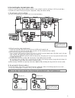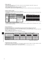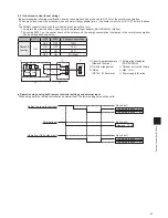
72
Installation
Installation
*4
Bottom case *3
Top case *2
Front cover *1
1. Component names and supplied parts
The following parts are included in the box.
Parts name
Qty.
Appearance
Remote controller (front cover)
1
Right figure
*1
Remote controller (top case)
1
Right figure
*2
Remote controller (bottom case)
1
Right figure
*3
Roundhead cross slot screws M×30
2
Wood screw .1×16
(for direct wall installation)
2
Installation Manual (this manual)
1
Simple Operation Manual
1
CD-ROM
(Instruction Book and Installation Manual)
1
* The front cover (*1) is already installed on the top case (*2) at factory ship-
ment.
*5 Remote controller cable is not included.
2. Field-supplied parts/Required tools
(1) Field-supplied parts
The following parts are field-supplied parts.
Parts name
Qty.
Notes
Double switch box
1
Not required for direct wall installation
Thin metal conduit
Necessary
Lock nut and bushing
Necessary
Cable cover
Necessary Required for routing remote controller cable along a wall
Putty
Reasonable
Molly anchor
Necessary
Remote controller cable
(Use a 0.3 mm² (AWG22) 2-core sheathed cable.)
Necessary
(2) Field-supplied tools
• Flat-tip screwdriver (Width: – 7 mm (5/32 – 9/32 inch))
• Knife or Nipper
• Miscellaneous tools
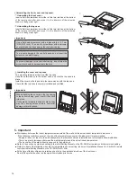
3. Selecting an installation site
This remote controller is for the wall installation. It can be installed either in the switch box or directly on the wall. When perform-
ing direct wall installation, wires can be thread through either back or top of the remote controller.
(1) Selecting an installation site
Install the remote controller (switch box) on the site where the following conditions are met.
(a) For connection to the indoor unit with an Auto descending panel, a place where people can check the Auto descending
panel operation of the indoor unit while they are operating the remote controller (Refer to the indoor unit Instructions Book
for how to operate Auto descending panel.)
(b) A flat surface
(c) A place where the remote controller can measure the accurate indoor temperature Sensors to monitor indoor temperature
are on the indoor unit and on the remote controller. When the room temperature is monitored with the sensor on the remote
controller, the main remote controller monitors the room temperature. When using the sensor on the remote controller, fol-
low the instructions below.
• To monitor the accurate indoor temperature, install the remote controller away from direct sunlight, heat sources, and the
supply air outlet of the air conditioner.
• Install the remote controller in a location that allows the sensor to measure the representative room temperature.
• Install the remote controller where no wires are routed around the temperature sensor on the controller.
(If wires are routed, the sensor cannot measure accurate indoor temperature.)
Summary of Contents for Mr.Slim PAR-30MAA
Page 2: ......
Page 92: ...MEMO ...
Page 93: ...MEMO ...
Page 94: ...MEMO ...
Page 95: ...MEMO ...
Page 96: ...MEMO ...
Page 97: ...MEMO ...
Page 98: ...MEMO ...
Page 99: ......

