78
Installation
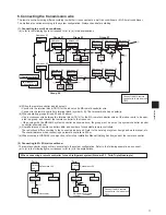
Standard 1:1
Standard 1:1
Twin
Twin
Ref address = 00
Outdoor
unit
Ref address = 00
Outdoor
unit
Ref
address
= 00
Outdoor
unit
Ref
address
= 01
Outdoor
unit
Indoor unit
Indoor unit
Indoor unit
Indoor unit
Indoor unit
Indoor unit
Main remote
controller
Main remote
controller
Main remote
controller
Sub remote
controller
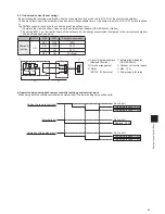
Standard 1:1
Twin
Triple
Outdoor
unit
Outdoor
unit
Outdoor
unit
Ref
address = 00
(Main)
Ref
address = 01
(Sub)
Ref
address = 02
(Sub)
Indoor unit
Indoor unit
Indoor unit
Indoor unit
Indoor unit
Indoor unit
Main remote
controller
Sub remote
controller
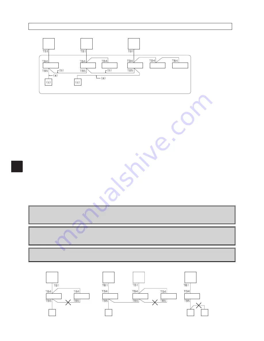
* The refrigerant address is set with the outdoor unit’s DIP switch. (Refer to the Outdoor Unit Installation Manual for details.)
* All indoor units enclosed in the box are controlled as one group.
(a) Wiring the remote controller and indoor unit
• Connect to the terminal block (TB5) for the indoor unit’s remote controller wire. (The terminal block has no polarity.)
• When using the simultaneous multi-type and different indoor unit models exist, always connect the remote controller to the
indoor unit having the most functions (wind speed, vane, louver, etc.).
(b) Wiring to group with different refrigerant systems
• Groups are formed with the remote controller cables. Use crossover wires between the remote controller terminal blocks (TB5)
of the main indoor unit in each refrigerant system to be grouped.
• If there are different indoor unit models in the same group, always use the outdoor unit to which the indoor unit with most
functions (wind speed, vane, louver, etc.) is connected as the main unit (refrigerant address = 00).
If the main unit is a simultaneous multi-type, make sure that the conditions in (a) above are satisfied.
• Up to 16 refrigerant systems can be controlled as one group using the MA remote controller.
(c) Up to two remote controllers can be connected to one group.
• If two remote controllers are connected to one group, always set the main remote controller and sub remote controller.
• If only one remote controller is connected to the group, always set the main remote controller. If two remote controllers are
connected to one group, set each remote controller as the main or sub remote controller. (Refer to the Installation Manual
(Setting Section.)
(d) Overall distance of remote controller cable
• The overall distance is 500m. Use a 0.3m
2
2-core cable for the remote controller cable. (Procure locally.)
The overall distance is 200m when two remote controllers are connected.
«Note»
Do not use a crossover wire between the remote controller terminal blocks (TB5) for the indoor units within the
same refrigerant system.
►The system may not operate correctly if a crossover wire is used.
When connecting to the remote controller terminal block (TB5) of the indoor unit, up to two wires having the same
size can be connected to one terminal block.
►Improper connections can result in contact defects or wire disconnection.
Do not use crossover wires between the remote controllers.
►Only one wire can be connected to the remote controller’s terminal block.
When grouping in different refrigerant systems
Summary of Contents for Mr.Slim PAR-30MAA
Page 2: ......
Page 92: ...MEMO ...
Page 93: ...MEMO ...
Page 94: ...MEMO ...
Page 95: ...MEMO ...
Page 96: ...MEMO ...
Page 97: ...MEMO ...
Page 98: ...MEMO ...
Page 99: ......


