8
System control (for Mr.Slim)
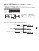
Refrigerant address No.
Initial setting: All switches are set to OFF (i.e., refrigerant address "0").
<SW1>
OFF ON
15
1
2
3
4
5
6
OFF ON
14
1
2
3
4
5
6
OFF ON
13
1
2
3
4
5
6
OFF ON
12
1
2
3
4
5
6
OFF ON
11
1
2
3
4
5
6
OFF ON
10
1
2
3
4
5
6
OFF ON
9
1
2
3
4
5
6
OFF ON
8
1
2
3
4
5
6
OFF ON
7
1
2
3
4
5
6
OFF ON
6
1
2
3
4
5
6
OFF ON
5
1
2
3
4
5
6
OFF ON
4
1
2
3
4
5
6
OFF ON
3
1
2
3
4
5
6
OFF ON
2
1
2
3
4
5
6
OFF ON
1
1
2
3
4
5
6
OFF ON
0
1
2
3
4
5
6
OFF ON
1
2
3
4
5
6
<Sequential Start Timer>
The refrigerant address also acts as a sequential start timer (one-second interval) to suppress the rush current.
The initial refrigerant address is 0. In this case, the sequential start timer is “0”, and the delay time is * 0 to 9.
Depending on the combination of the No. 3 to 6 switch settings, the units can be sequentially started at one-second intervals be-
tween 1 to 15 (delay time is 10 to 2).
* Differs according to the remote controller operation timing.
(Example) Sequential start timer 12 = 8 +
→
Switch No. 5 and 6 ON
Refrigerant address setting and sequential start timer following SW1 (No. 3 to 6) switch operations
Setting details
1 2 3 4 5 6
ON
1 2 3 4 5 6
ON
1 2 3 4 5 6
ON
1 2 3 4 5 6
ON
Refrigerant address
1
2
8
Sequential start timer
1
2
8
Delay timer (Sec.)
10
11
13
17
: Indicates switch position
<Confirming the outdoor unit address>
To determine which outdoor unit corresponds to the designated refrigerant address, designate the refrigerant address with the
self-diagnosis mode. The designated outdoor fan will run intermittently.
With the initial setting (refrigerant address 0), the sequential start timer is “0” and the delay time is * 0 to 9.
<Work procedures>
• Connect the remote controller to one of the indoor units, and connect each refrigerant system with a crossover wire.
Always wire from the indoor unit.
• Set the refrigerant address for each outdoor unit, and turn the power ON.
Set the refrigerant address before turning the power ON.
* The power for the remote controller is supplied from the address 00 indoor unit. (LED2 on the indoor control board will light.)
<Outdoor unit address setting>
• For group control, an address must be set for each outdoor unit.
• To set addresses to outdoor units, use the DIP switch SW1 (3-6) provided on each outdoor control board (Initial setting: All are
set to "OFF".)
• Address setting by SW1 is as follows.
Function
Operation by switch
ON
OFF
SW1
Function
selection
1 Forced defrosting
Start
Normal
2 Error history clear
Clear
Normal
3 Refrigerant address setting
↑
↑
↑
Used to set outdoor
unit addresses
("0" to "15").
5
6
* Checking the outdoor unit refrigerant addresses
To find the location of an outdoor unit with a specific refrigerant address, specify the address in self-diagnosis mode. The out
-
door unit will operate intermittently.
Summary of Contents for Mr.Slim PAR-30MAA
Page 2: ......
Page 92: ...MEMO ...
Page 93: ...MEMO ...
Page 94: ...MEMO ...
Page 95: ...MEMO ...
Page 96: ...MEMO ...
Page 97: ...MEMO ...
Page 98: ...MEMO ...
Page 99: ......

