71
14
DISASSEMBLY PROCEDURE
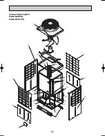
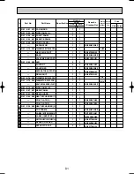
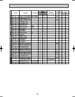
OPERATING PROCEDURE
PHOTOS
PUHZ-RP8YHA PUHZ-RP10YHA
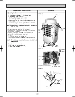
Photo 1
(front)
Photo 2
(rear)
Service panel
fixing screw
(8pcs)
Front panel
fixing screw
(7pcs)
Front panel
1. Removing the service panel
(1) Remove 8 service panel fixing screws (5
o
10)
(see photo 1) .
(2) Remove the service panel by sliding it towards you.
w
It is the panel to remove when you maintain
the refrigerant circuit, electrical parts, and compressor.
2. Removing the rear panel
(1) Remove 7 rear panel fixing screws (5
o
10) (see photo 2).
(2) Remove the rear panel by sliding it towards you.
w
It is the panel to remove when you maintain the machine
room from the rear side.
3. Removing the front panel
(1) Remove 7 front panel fixing screws (5
o
10) (see photo 1).
(2) Remove the front panel by sliding it towards you, then upward.
w
It is the panel to remove when you maintain the thermistor
and the fan motor.
w
When servicing, pay careful attention in removing heavy parts.
w
Collect the refrigerant before you service the refrigerant system.
w
When brazing, make sure to apply the non-oxidizing braze.
Rear guard
Rear guard
fixing screw
(7pcs)
Rear panel
Rear panel
fixing screw
(7pcs)
Servis panel
OC317-3.qxp 04.11.26 9:41 AM Page 71


