19
±
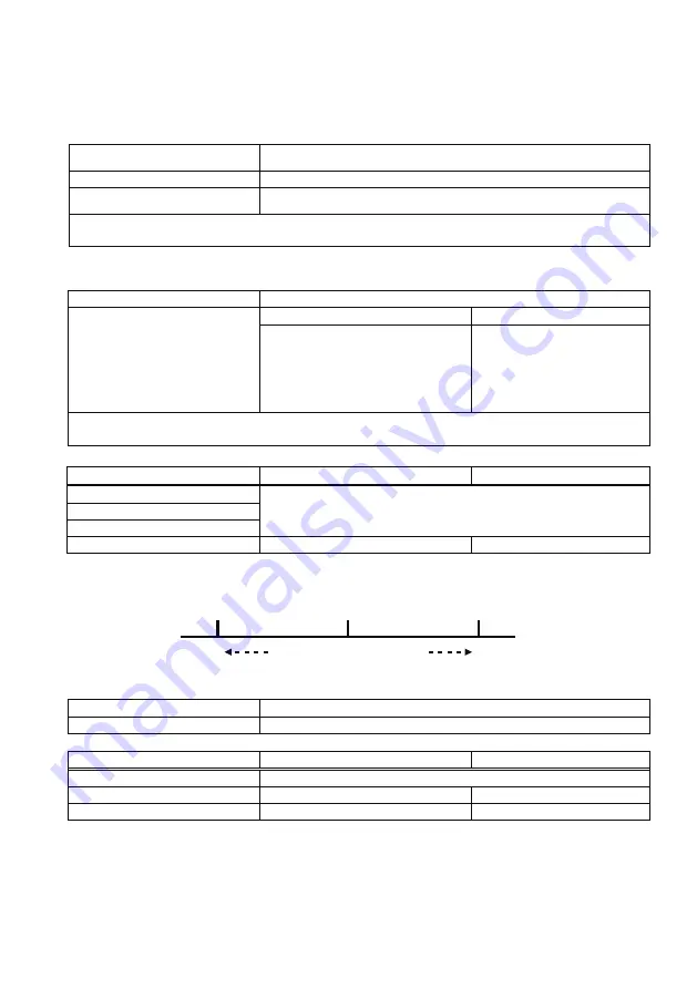
2.0% of actual value for V (100 V to 440 V)
×
I (5 to 100% of In) (PF = 1)
±
2.5% of actual value for V (100 V to 440 V)
×
I (5 to 100% of In) (PF = 0.5)
±
3.0% of actual value for V (100 V to 440 V)
×
I (10 to 100% of In) (PF = 0)
0 to 99999.9 kWh/kvarh (250 A frame)
0 to 999999 kWh/kvarh (400/800 A frame)
Electric energy accuracy
Range
●
The electric energy and reactive energy are measured if the electric current measurement value is around 0.4% or higher.
●
If this exceeds 999999 kWh/kvarh addition will continue with the value reset to 0 kWh/kvarh.
(4) Electric energy/Reactive energy
[1] The integrated value is the cumulative total value, from when usage began (after previous reset) to now. (The electric energy during reverse power
flow is not added.)
[2] The electric energy and reactive energy can be set to any value.
[3] The latest one hour amount is the one hour amount from one hour to the next hour as measured by the internal clock. (It is the latest one hour
amount only.)
[4] The one hour amount maximum value is the maximum value of the latest one hour amount, from when usage began (after previous reset) to now.
[5] The measurement range and measurement accuracy for the electric energy and reactive energy are shown below.
±
2.5% of actual value
0.0, 45.0 to 65.0 Hz
Accuracy
Range
(6) Frequency
[1] The measurement accuracy and measurement range for the frequency are shown below.
Display
0.0 Hz
Communication
V12 and V32 are 0 V (less than 22 V)
Less than 45 Hz
65 Hz exceeded
Blinks at 45.0 Hz
Blinks at 65.0 Hz
Fixed at 45.0 Hz
Fixed at 65.0 Hz
[2] Display/communication values will be as follows in the following conditions.
±
5% for an electric angle of 90
°
Display
LEAD (forward) 50%
to
100%
to
50% LAG (delay)
forward displays
“
LEAD
”
while delay displays
“
LAG
”
Communication
LEAD (forward) 0%
to
100%
to
0% LAG (delay)
forward is a negative value
(values under 50% are reference values)
●
Power factor is measured for all phases combined. If 0 A is displayed because the electric current measurement value for a 1-phase was
cut-off for the load current near cut-off, the measurement error could increase.
Accuracy
Range
[3] Power factor sizes are shown below.
(5) Power factor
[1] The measurement accuracy and measurement range for the power factor are shown below.
100.0%
-50.0%
50.0%
LEAD
LAG
[2] Display/communication values will be as follows in the following conditions.
Display
100%
Communication
–
I1, I2 and I3 are 0 A (less than 1.0% of In)
V12 and V32 are 0 V (less than 22 V)
P is 0 kW
Blinks at 50%
PF exceeds measurement range
Large
Small
Reactive energy accuracy
Summary of Contents for NF400-HEW
Page 55: ......
Page 56: ...LN107A329H02 IB63E31 A 1911 MEE MDU Breakers Nov 2019 ...


