Wiring method
•
Address setting method
a. Indoor/outdoor transmission line
Apply jumper wiring connection between M1, M2 terminals of the indoor/outdoor transmission line terminal block
(TB3) on the outdoor unit (OC) and that of indoor/outdoor transmission line terminal block (TB5) on each indoor
unit (IC). (with non-polarity two wires)
❉
When the transmission line is long or noise sources are located near the unit, recommend to use shielded wire.
Connection of shielded wire:
For the earth of shielded wire, apply jumper wiring connection between the earth screw of OC and the S-terminal of
IC terminal block (TB5).
b. Centralized control transmission line
Connection is not required.
c. MA remote controller wiring
Connect the 1, 2 terminals of MA remote controller wiring terminal block (TB15) on IC to the terminal block of MA
remote controller (MA). (with non-polarity two wires)
❉
MA remote controller can be connected to A-type indoor unit or later.
For 2-remote controller operation:
To employ 2-remote controller operation, connect 1, 2 terminals of the terminal block (TB15) on IC to the terminal
block of two MA remote controllers.
❉
Set the main/sub selector switch of one MA remote controller to the sub remote controller. (For the setting method,
see the installation manual of MA remote controller.)
For indoor group operation:
For the group operation of IC, connect 1, 2 terminals of the terminal block (TB15) on all ICs within the same group,
and connect 1, 2 terminals of the terminal block (TB15) on another IC to the terminals of MA remote controller.
(with non-polarity two wires)
❉
To operate the indoor units with different function in the same group, refer to 1. (2).
d. LOSSNAY connection
Apply jumper wiring to connect M1, M2 terminals of the terminal block (TB5) on IC to the indoor/outdoor
transmission terminal block (TB5) on LOSSNAY (LC). (with non-polarity two wires)
❉
Linked and registered automatically with all indoor units within a refrigerant system.
❉
Please refer to the 1. (2) “Manual address set-up,” when interlocking partial indoor units with Lossnay, using
Lossnay alone without interlocking, interlocking indoor units and Lossnay for over 16 units within a refrigerant
system, or connecting LOSSNAY for over 2 units in a refrigerant system.
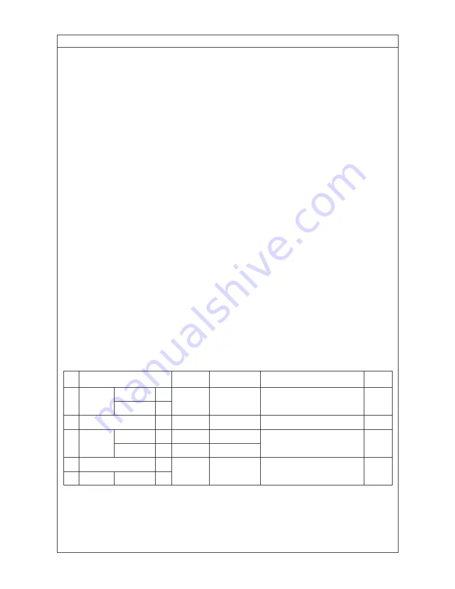
e. Switch setting
Address setting is not required.
Order
Unit or controller
Address
Setting method
Caution
Factory
setting range
setting
Main unit
IC
Not required
–
00
1
Indoor unit
Sub unit
IC
2
LOSSNAY
LC
Not required
–
3
MA remote
Main uni
Hex. unit
t
MA
Not required
–
Main
controller
Sub unit
MA
Sub unit
4
Outdoor unit
OC
Not required
–
5
Sub unit
OS
• Refer to 1. (2)
to operate indoor units
with different function in the same
group.
Set with main/sub
selector switch.
00
00
- 22 -


