- 31 -
IC
TB5
TB15
1 2
01
101
103
102
IC
TB5
TB15
1 2
02
A1 B2
RC
A1 B2
RC
TB5
05
IC
TB5
1 2
TB15
IC
TB5
TB15
1 2
04
03
TB5
06
A1 B2
RC
L3
L4
L23
L24
NO
L2
L22
OC
TB3
TB7
51
OC
TB3
TB7
53
L31
A B S
L32
NO
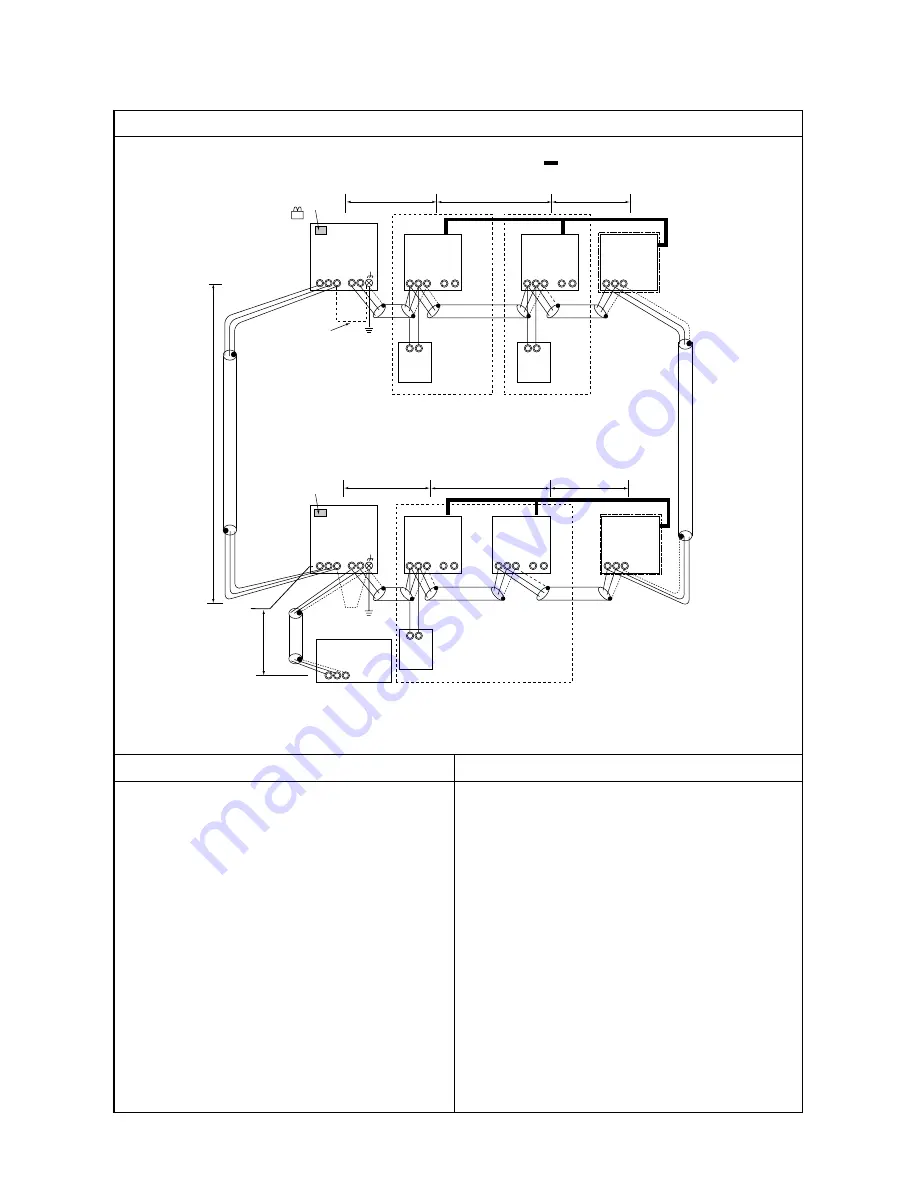
Control wiring example
Group
Prohibited items
Allowable length
Interlocking with ventilation
– Example to use shielded wire –
Group
Group
LC
LC
Note 2
Note 1
Note 1
System controller
Connect
CN41
→
CN40 Replace
SW2-1 OFF
→
ON
Leave CN41 as it is.
SW2-1 OFF
→
ON
Note 1: If only the LM adaptor is connected, leave SW2-1 to OFF.
Note 2: LM adaptor requires single phase AC 230 V.
1. A group of indoor units cannot be connected to both M-NET
remote controller and MA remote controllers.
2. No more than 2 M-NET remote controllers can be connected
to a group of indoor units.
3. Do not connect the TB5
’
s (Terminal block) of the indoor
units that are connected to different outdoor units.
4. Replace CN41 (power supply switch connector on outdoor
units) on only one of the outdoor units.
5. Ground the S terminal of TB7 on only one of the outdoor
units.
6. Transmission line booster is necessary when the total
number of connected indoor units exceeds 20 (19 with 1 BC
and 18 with 1 BC and BS each).
7. Transmission line booster is necessary if the system
includes indoor units of 200 or higher and the total number
of indoor units exceeds 16 (15 with 1 BC and 14 with 1 BC
and BS each).
a. Indoor/outdoor transmission line
b. Centralized control transmission line
c. M-NET remote controller wiring
The same as 2. (1)
The same as 1. (4)
The same as 1. (3)
S
M1M2
S
M1M2
S
M1M2
S
M1M2
M1M2
S
M1M2
S
M1M2
S
M1M2
S
M1M2
M1M2
2. System Using the M-NET Remote Controller
(1) System with the system controller connected to the transmission lines for centralized control


