11
Medical Video Signal
1
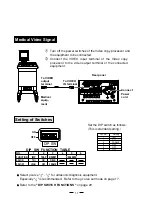
Turn off the power switches of the Video copy processor and
the equipment to be connected.
2
Connect the VIDEO input terminal of the Video copy
processor to the video output terminal of the connected
equipment.
Rear panel
Medical
equip-
ment
AC LINE
REMOTE
ON
OFF
VIDEO
IN
OUT
DIP SW
DIP SW FUNCTION TABLE
NO.
1
2
3
4
5
6
FUNCTION
IMP
TRAP
MEMORY
RESERVED
SW-ON
75
Ω
ON
FIELD
SW-OFF
HIGH
OFF
FRAME
Set the DIP switch as follows:
(This is standard setting.)
DIP SW FUNCTION TABLE
NO.
1
2
3
4
5
6
FUNCTION
IMP
TRAP
MEMORY
RESERVED
SW-ON
75
Ω
ON
FIELD
SW-OFF
HIGH
OFF
FRAME
Setting of Switches
2
Select
γ
-curve " " - " " for ultrasonic diagnosis equipment.
Especially " " is recommended. Refer to the
γ
-curve set mode on page 17.
2
Refer to the " DIP SWITCH FUNCTIONS " on page 29 .
To VIDEO
output
terminal
To VIDEO
IN terminal
Connect
Power
cord
ON
OFF
DIP SW
SW-NO.
Setting
75
Ω
OFF
FRAME
OFF
OFF
OFF
1
2
3
4
5
6


