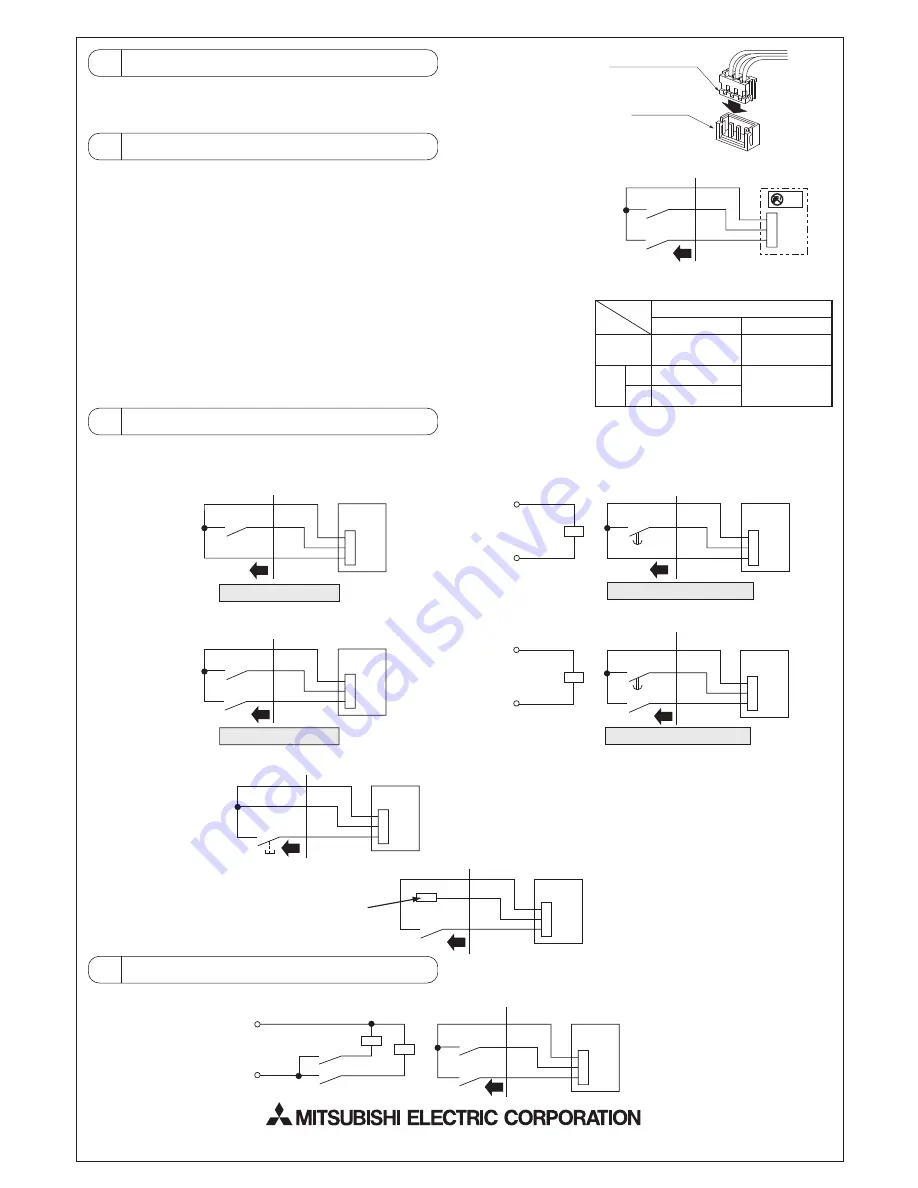
3 Connecting to the Indoor Unit
1. Connect to the connector CN32 on the indoor controller board.
2. Press the connector for the remote ON/OFF adaptor into the CN32 connector.
The connector can only be connected in one direction only. Do not force the connection.
4 Locally Procured Wiring
With the remote ON/OFF adaptor, variations of connection method with the locally
installed circuit will provide different types of operating configurations.
Example: External timer operation, remote control operation
1. Basic Connection Method
SW1 - Operating switch
Performs operation/stopping of indoor unit.
SW2 - Selecting switch
For selecting whether the operation/stopping is to be performed by external circuit
or remote control.*
* Also includes system controller (central controller).
2. Switch Settings (Refer to table at right for details.)
5 Examples of Usage
6 Wiring Restrictions
For remote operation
CN32
Orange
Red
Brown
Local wiring
For remote timer operation
CN32
Orange
T
Red
Brown
Local wiring
Indoor controller board
For remote operation
CN32
Orange
Red
Brown
Local wiring
CN32
Orange
Red
Brown
Local wiring
SW1
SW1
Power supply for
external timer
For remote timer operation
CN32
Orange
Red
Brown
Local wiring
Power supply for
external timer
SW2
SW2
CN32
Orange
Red
Brown
Local wiring
SW2
SW2
Since this is not used, be sure to
completely wrap with insulation tape
If SW2 is on, operation cannot be performed
by the remote controller.
If SW2 is off, operation is permited.
Use a momentary switch (a switch that is turned on manually and
turns off automatically) for SW2.
Press SW2 (for 1 second or more) and the operation starts. After
this, the remote controller can be used for operations.
In either case, there is a 5 to 6 second delay from the time when the operating command is sent until the unit operates.
1. To perform operation/stopping by only remote operation or external timer and to prohibit operation/stopping by the remote
controller, use the following circuits.
2. To perform operation/stopping by remote operation or external timer and allow operation/stopping by the remote
controller, use the following circuits.
3. To start operation by remote operation and then freely use remote controller, use the following circuit.
4. To permit/prohibit the use of the remote
controller by an external circuit.
Indoor controller board
Indoor controller board
Indoor controller board
Indoor controller board
Indoor controller board
T
T
T
SW2
ON
OFF
SW1
ON
OFF
Remote
controller
Cannot perform
operation/stopping
Can perform
operation/stopping
Operation
Stopping
Cannot perform
operation/stopping
Indoor controller
board
CN32
Orange
Red
Brown
Local wiring
SW1
SW2
ELV
SW2 - If on.
• Operation/stopping cannot be controlled from
remote controller.
Other operations (such as temperature settings
and changing fan speed) can be performed.
• Operation/stopping can be performed by SW1.
SW2 - If off.
• Operations can be performed
from remote controller.
• Operation/stopping cannot be
performed by SW1.
2
3
Remote ON/OFF adaptor
CN32 connector
CN32
Orange
Red
Brown
Local wiring
Power supply
X2
X1
SW2
SW1
Indoor controller board
X1
X2
Keep the length of wire from the circuit board of the indoor unit within 10 meters. Excessive length could cause improper operation.
Use a transit relay when extending wiring such as remote wiring.
HEAD OFFICE:
TOKYO BLDG., 2-7-3, MARUNOUCHI, CHIYODA-KU, TOKYO 100-8310, JAPAN
Authorized representative in EU:
MITSUBISHI ELECTRIC EUROPE B.V.
HARMAN HOUSE, 1 GEORGE STREET, UXBRIDGE, MIDDLESEX UB8 1QQ, U.K.


