background image

– 14 –

GB

- When LOSSNAY or OA processing unit are not registered

4

If registration is unnecessary, end registration by pressing and holding down the 

 and  

 buttons at the same time for two seconds.

If a new LOSSNAY or OA processing unit must be registered, go to step 

1. Registration 

procedure

If you want to confirm another LOSSNAY or OA processing unit, go to step 

2. Confirmation 

procedure

. To delete a registered LOSSNAY or OA processing unit, go to step 

3. Deletion 

procedure

.

<1. Registration procedure>

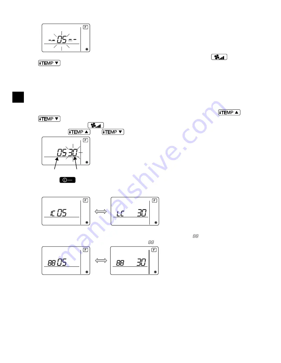
5

Set the address of the indoor unit to be interlocked with the LOSSNAY unit using the 

 and 

 buttons. (01 to 50)

6

After setting, press the 

 button and set the Lossnay address you want to register by 

operating the 

 and 

 buttons. (01~50)

7

Press the 

 button, and register the set indoor unit address and LOSSNAY address.

- Registration end display

The indoor unit address and “IC” and LOSSNAY address and “LC” are alternately displayed.

- Registration error display

If the address is not registered correctly, the indoor unit address and [

], and the registered 

LOSSNAY (or OA processing unit address) and [

] are alternately displayed.

Cannot be registered because the registered indoor unit or LOSSNAY or OA processing unit does 

not exist.

Cannot be registered because another LOSSNAY or OA processing unit was registered at the 

registered indoor unit.

..

..

..

..

..

Indoor unit address

LOSSNAY or OA processing unit address

ON

OFF

WT06592X01.book  Page 14  Monday, April 16, 2012  10:38 AM

Summary of Contents for PAC-YT52CRA

Page 1: ...ctric work must be performed by qualified personnel Do not install the unit in a place where large amounts of oil steam organic solvents or corrosive gases such as sulfuric gas are present or where acidic alkaline solutions or sprays are used frequently These substances can compromise the performance of the unit or cause certain components of the unit to corrode which can result in electric shock ...

Page 2: ...n the cables so as not to stress the terminals Improperly connected cables may break overheat and cause smoke or fire To reduce the risk of injury or electric shock switch off the main power before performing electrical work All electric work must be performed by a qualified electrician according to the local regulations standards and the instructions detailed in the Installation Manual To reduce ...

Page 3: ...s in hospitals or facilities with radio communication capabilities Inverter high frequency medical or wireless communication equipment as well as power generators may cause the air conditioning system to malfunction Air conditioning system may also adversely affect the operation of these types of equipment by creating electrical noise To avoid malfunctions do not bundle power cables and signal cab...

Page 4: ...Lock nut and bushing Necessary Cable cover Necessary Required for routing remote controller cable along a wall Putty Reasonable Molly anchor Necessary Remote controller cable Use a 0 3 mm AWG22 2 core sheathed cable Necessary Parts name Qty Appearance Remote controller top case 1 Right figure 1 Remote controller bottom case 1 Right figure 2 Roundhead cross slot screws M4 30 2 3 Wood screw 4 1 16 f...

Page 5: ...l of two can be connected to a group made up of indoor units NOTE When using this Simple MA remote controller in combination with other MA remote controllers be sure to follow the compatibility rules below 4 How To Wire Transmission Line Connect to TB15 on the indoor unit a Outdoor unit b Indoor unit c LOSSNAY or OA processing unit d Main Remote Controller e Sub Remote Controller f Central control...

Page 6: ...he most functions wind velocity vane louver etc 2 When grouping with difference refrigerant systems Group using the remote controller wiring Connect the remote controller to an arbitrary indoor unit of each refrigerant system you want to group When mixing different types of indoor units in the same group always make the outdoor unit connecting the indoor unit with the most functions wind velocity ...

Page 7: ...monitored with the sensor on the remote controller the built in sensor on the Main remote controller monitors the room temperature When using the sensor on the remote controller follow the instructions below Indoor unit function Main remote controller Sub remote controller Compatibility Models applicable for AUTO dual set point mode This Simple MA remote controller This Simple MA remote controller...

Page 8: ...l a hole in the wall and thread the cable through it 2 Seal the cable access hole with putty Installation using a switch box Seal the remote controller cable access hole at the connection of switch box and conduit tube with putty Do not install the controller in a place where the difference between the remote controller surface temperature and the actual room temperature will be great If the tempe...

Page 9: ...p case Bottom case 16 21 32 6 1 4 Sheath Unit mm in Connect the cable non polarized 2 core wire must not be seen on the back Insert the sheathed part of the cable inside the case and then secure the cable Seal the gap with putty Route the cable behind the remote controller Remote controller cable To reduce the risk of electric shock shorting or malfunctions keep wire pieces and sheath shavings out...

Page 10: ...f the top case Remote controller Main Sub and other function settings are performed using these switches Ordinarily only change the Main Sub setting of SW1 The factory settings are ON for SW1 2 and 3 and OFF for SW4 Installation using a switch box Direct wall installation Setting the dip switches SW No SW contents Main ON OFF Comment 1 Remote controller Main Sub setting Main Sub Set one of the two...

Page 11: ...t malfunctions do not remove the protective sheet or the circuit board from the top case To prevent cable breakage and malfunctions do not hang the top controller casing hang by the cable as shown in the figure above Important Clamp Insert the wires Hold the wires in place with the clamp to prevent undue force from being applied to the terminal block and causing cable breakage Important Wall Shoul...

Page 12: ...tip screwdriver with a blade width of 3 5 mm 1 8 7 32 inch into the latches at the bottom of the remote controller and lift the latches Then pull up the top case Seal the gap with putty Use a cable cover Thread the cable through the top of the remote controller To prevent damage to the controller casing do not force the flat tip screwdriver to turn with its tip inserted in the slot Do not insert t...

Page 13: ...roller button 2 Press and hold down the and buttons at the same time for two seconds The display shown below appears The remote controller confirms the registered LOSSNAY or OA processing unit addresses of the currently connected indoor units 3 Registration confirmation result The indoor unit address and registered LOSSNAY or OA processing unit address are displayed alternately 6 Test Run 7 Ventil...

Page 14: ...tons 01 to 50 6 After setting press the button and set the Lossnay address you want to register by operating the and buttons 01 50 7 Press the button and register the set indoor unit address and LOSSNAY address Registration end display The indoor unit address and IC and LOSSNAY address and LC are alternately displayed Registration error display If the address is not registered correctly the indoor...

Page 15: ...ted Registered indoor unit address does not exist 3 Deletion procedure Use this procedure when you want to delete registration of indoor units connected by the remote controller and LOSSNAY or OA processing unit 0 Confirm see 2 Confirmation procedure the LOSSNAY or OA processing unit you want to delete and display the indoor units and LOSSNAY or OA processing unit confirmation results a Press the ...

Page 16: ...r air intake by the indoor units 2 Connected with outdoor air intake by the indoor units 3 04 Power voltage 240 V 1 220 V 230 V 2 07 Filter sign 100 hours 1 Set 01 to 04 or AL for the Unit number These settings apply to each indoor unit If 01 02 03 04 is set for the Unit number the settings apply only to the specified indoor unit regardless of the number of connected indoor units one through four ...

Page 17: ...ay shown below 3 Set the outdoor unit refrigerant address No When the B and C buttons are pressed the refrigerant address No decreases and increases between 00 and 15 Set it to the refrigerant address No whose function you want to select This step is unnecessary for single refrigerant system 1 Check the function selection set contents 2 Switch to the FUNCTION SELECTION mode Press D and C simultane...

Page 18: ... F is displayed at the unit address No display and when it flashes together with the refrigerant address display the selected unit address No does not exist Correctly set the refrigerant address and unit address No by repeating steps 3 and 4 When registered using the A the registered indoor unit begins fan operation When you want to know the location of the indoor units of the unit address No whos...

Page 19: ...s near the transmission line 9 To select more functions press the D and repeat steps 3 to 8 0 End function selection Press and hold down the C and D buttons at the same time for two seconds or longer After a while the function selection display disappears and the remote controller returns to the air conditioner off display Do not operate the air conditioner from the remote controller for 30 second...

Page 20: ...Press the button to stop the operation of the air conditioner 2 Press and hold down the and the buttons at the same time for two seconds or longer to check the current settings 3 When the response has been received from the indoor unit the current settings appear If there is no response nothing appears Make this setting only when the function settings need to be changed on CITY MULTI This setting ...

Page 21: ...se settings to be checked ALL 1 to 50 3Press the button then press the and the buttons to set the Function Setting No to be checked 000 to 255 4Press the button to display the current Function Setting Value ON OFF 2 sec Response has been received Indoor unit address setting Function Setting No setting Function Setting Value setting The setting for the specified Function Setting No has not been com...

Page 22: ... decreases and increases between 01 and 50 or 00 and 15 Set it to the address No or refrigerant address No you want to self diagnosis 10 Self diagnosis Response has been received Indoor unit address setting Function Setting No setting Current setting value No response The setting for the specified Function Setting No has not been completed The specified indoor unit does not exist Waiting for respo...

Page 23: ...iagnosis Press the A button Self diagnosis resets and indoor units stop When operation is prohibited this operation is ineffective 1 First check the power mark When normal voltage DC12V is not applied to the remote controller the power mark goes off When the power mark is off check the remote controller wiring and the indoor unit 2 Switch to the remote controller check mode When the B button and D...

Page 24: ...te controller Error display 2 E3 6833 6832 flash Cannot send Error display 3 ERC and data error count are displayed Data error generation There is noise on the transmission line or the indoor unit or another remote controller is faulty Check the transmission line and the other remote controllers Data error count is the difference between the number of bits of remote controller send data and the nu...

Reviews: