


10
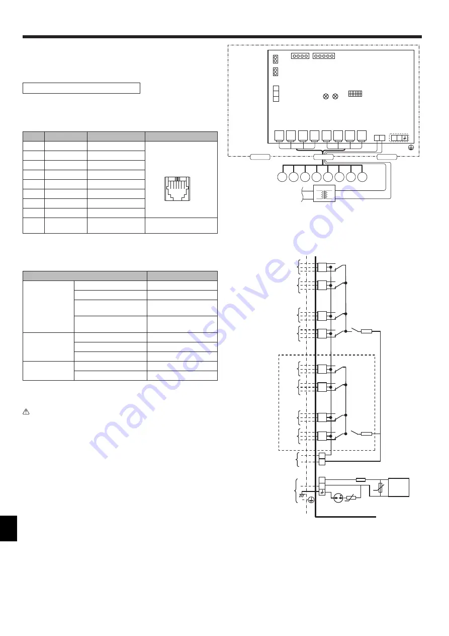
Connect the damper motor cable to CN61 to CN68.
The damper motor is powered via TB24.
ZONE CONTROL INTERFACE
CN62
N
L
3
2
1
TB3AC
TB3M
TB24
CN61
CN64
CN63
CN66
CN65
CN68
CN67
SW1
ON
1
8
LED2
LED1
CN506
(RED)
CN460
(WHT)
CN201
(RED)
CN202
(RED)
ZONE
MOTOR
ZONE
MOTOR
ZONE
MOTOR
ZONE
MOTOR
ZONE
MOTOR
ZONE
MOTOR
ZONE
MOTOR
ZONE
MOTOR
24 V AC
220‒240V AC
P
R
I
MA
R
Y
SE
C
O
ND
A
R
Y
<Fig. 4.2.6>
<Fig. 4.2.5>
Refer to the following table to connect the cable to the correct zone.
Use the cable with proper pin assignment.
External outputs
Name Terminal block
Item
Connector type
Zone1
CN61
Damper moter output1
PIN1,2:OPEN, PIN3,4:COM,
PIN5,6:CLOSE
Zone2
CN62
Damper moter output2
Zone3
CN63
Damper moter output3
Zone4
CN64
Damper moter output4
Zone5
CN65
Damper moter output5
Zone6
CN66
Damper moter output6
Zone7
CN67
Damper moter output7
Zone8
CN68
Damper moter output8
AC24V
TB24
24V AC damper
source supply
no polarity
Ensure that the damper motor and the damper motor cable to be used
meet the following specification.
Locally supplied parts
Specification
Damper motor
Voltage
24V AC
Frequency
50Hz/60Hz
Maximum Operation Current
(per damper)
360mA or less
Maximum Electric Power
(per damper)
7VA or less
Damper motor
cable
Wire diameter (mm²)
0.48mm² or more
Maximum wiring length
30m or less
Type
RJ12 6-poler, 6-core
Transformer *1
Input Voltage
240V AC
Output Voltage
24V AC
*1 The size or power supply method shall be selected properly depending on the
type of the damper motor and the damper motor cable to be used.
Caution: Wiring size must comply with the applicable local and national
codes.
When connecting damper motors, ensure to connect them sequentially starting
from zone 1.
<Damper motors>
TB3AC
SA01
NR02
NR01
311-
339V DC
F1
ZONE7
ZONE8
F3
ZONE5
ZONE6
ZONE4
ZONE3
ZONE2
ZONE1
X605
X607
X608
X602
X603
X601
604
X606
X609
610
F2
TB24
Power supply
Power supply
24V AC
220-240V AC
N
L
CN61
CN62
CN63
CN64
CN66
CN67
CN68
CN65
U
U
Only 8zone model
Do not connect the 240V AC cable to TB24.
1 2 3 4 5 6
4. Zone Control Interface


