11
4. Zone Control Interface
4.2.2
240V damper motor model [PAC-ZC40H-E / PAC-ZC80H-E]
<Routing>
All electrical work shall be carried out by a suitably qualified technician. Failure to comply with this could lead to electrocution, fire, and death. All wiring must be conducted
according to the national wiring regulations.
Connections should be made to the terminals indicated in the following figures depending on the voltage.
When terminating cables to terminal bed, please use electrical lugs.
Notes:
1. Do not run the low voltage cables through a slot that the high voltage cables go through.
2. Do not bundle power cables and damper cables together with other cables.
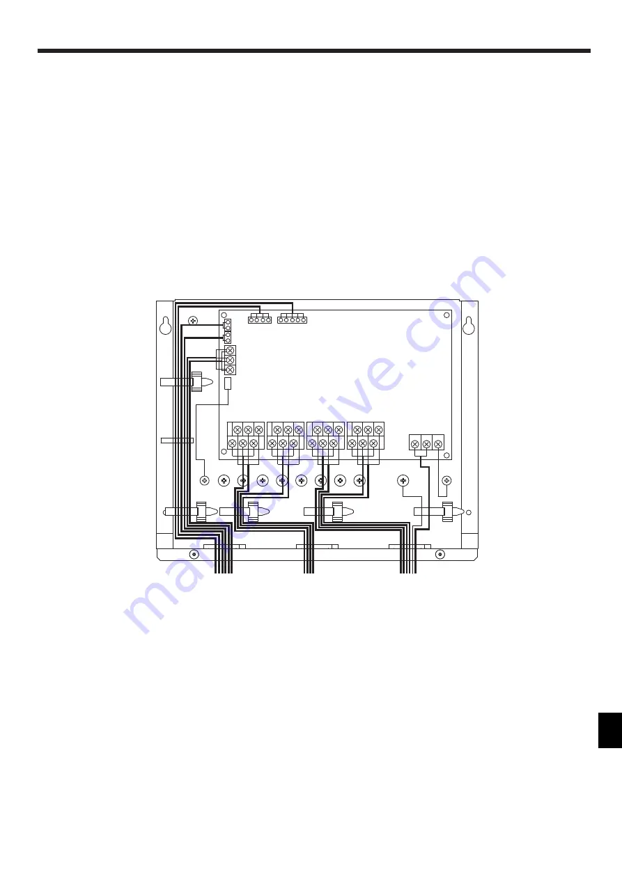
3. Bundle cables as Fig. 4.2.7 by using clamps.
4. Remote controller cables, sensor cables, and other cables should be segregated by more than 50mm from each other until entry into the zone control inter
-
face. Also avoid cables running along metal surfaces.
<Fig. 4.2.7 >
Wiring for the zone controller 240V damper model
• Damper cables 1
–4
• Power cables (240V)
• Damper cables 5-8
• Indoor unit
• Remote Controllers
• Sensors
• Wi-Fi Interface


