15
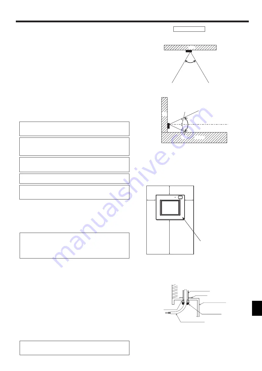
<Fig. 5.1.3>
<Fig. 5.1.4>
Occupancy sensor detects occupancy based on the temperature difference be-
tween the occupant and its surroundings.
The occupancy sensor is designed to detect the changes in the amount of infrared
light emitted from an object in the detection area, including human bodies.
The occupancy sensor will not detect occupancy if no movements exist.
The sensor also becomes less sensitive to occupancy when the temperature differ-
ence between the occupant and its surroundings is small.
Select the installation location carefully to avoid false detection.
Factors that contribute to false detection by the occupancy sensor
• Direct sunlight to the remote controller
• Supply air directed straight toward the remote controller
• Fireplace in the detection zone
• Portable heater (e.g., oscillating electric heater) in the detection area
• Excessive vibrations or large impact inflicted on the remote controller
• Strong electrical noise
• Movements of small animals, such as cats and dogs
The remote controller can be installed either on a mounting block or directly on the
wall. Perform the installation properly according to the method.
1
Drill a hole in the wall.
■ Installation using a mouting block
• Drill a hole in the wall, and install the mouting block on the wall.
• Connect the mouting block to the conduit tube.
■ Direct wall installation
• Drill a hole in the wall, and thread the cable through it.
Note: No cable access hole is required when running the remote controller
cable along the wall.
2
Seal the cable access hole with putty.
■ Installation using a mouting block
• Seal the cable access hole at the connection of mouting block and conduit
tube with putty
5. Zone Remote Controller
Required space around the remote controller
To reduce the risk of electric shock, malfunctions, or fire, seal the gap between
the cables and cable access holes with putty.
Use caution when handling circuit boards to prevent damage from static elec
-
tricity.
Although the circuit board is covered with an insulation sheet, part of the cir-
cuit board is exposed. Use extra caution not to let your fingers come in contact
with the circuit board.
Important
n
o
it
c
e
ri
d
l
a
c
it
r
e
V
n
o
it
c
e
ri
d
l
a
t
n
o
z
ir
o
H
44°
Remote
controller
Wall
44°
22°
22°
Remote
controller
Floor
Wall
Brightness sensor
<Fig. 5.1.2>
Handling precautions
• Keep the lens scratch-free.
• Do not place adhesive tape or labels over the lens.
• Use a soft cloth to clean the lens.
Do not use solderless terminals to connect cables to the terminal block.
Solderless terminals may come in contact with the circuit board and cause
malfunctions or damage the controller cover.
To avoid deformation and malfunction, do not install the remote controller in
direct sunlight, where the ambient temperature may rise above 40ºC (104°F)
or drop below 0ºC (32°F), or where the relative humidity
may rise above 90% or drops below 20%.
To reduce the risk of malfunctions, do not install the controller in a place where
water or oil may come into contact with the controller, or in a condensing or
corrosive environments.
Do not install the remote controller directly onto electrically conductive objects
such as metal plate that has not been painted.
To use the Energy Saving Assist function in a system with both main and sub
remote controllers, activate the function only on the remote controller whose
coverage area is the largest.
Important
30
(1-3/16)
30
(1-3/16)
30 (1-3/16)
120 (4-3/4)
Temperature sensor
unit: mm (in)
Wall
Conduit tube
Locknut
Mouting block
Seal the gap
with putty.
Remote
controller cable
Bushing


