25
8. Initial setting
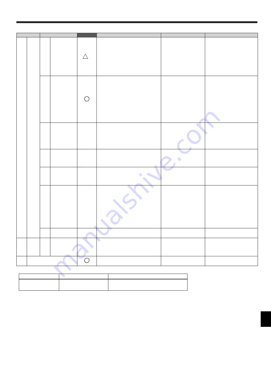
■Service menu items
*1 When connecting the zone control interface to PEA-RP
·
GAA model, set the air conditioning unit as the following table.
Unit
Function number
Function setting
IC
(Air conditioning units)
02
(Indoor temperature detecting)
2
(Set by indoor unit's remote controller)
*2 The LED indicates the operation status of air conditioning units in colors. Refer to "LED Indicator" in the instructions book.
*3 All settings information will be cleared to the default.
[Data backup during power failure]
All the data for items except items (1)-(g) Reset RC, and (3) Test run are nonvolatile, and will be
backed up even during power failure.
Data for items (1)-(a), and (2)-(a) will be backed up on the air conditioning unit or zone control interface side.
Item
Detail
Mandatory
Description
Setting
Default
(1)
Setup
(a)
Function setting
*1
Use to make the settings for the indoor
units and Zone Control Interface from the
controller.
•
Refer to (1) Set menu
a) Function setting in page 26
• Refer to "8.3. Function
setting of zone control
interface".
• Refer to the indoor unit
installation manual for the
detailed explanation of the
setting items.
—
(b)
Zone setting
Set the following contents:
• Existence of “Sub RC”, “Option
Sensor1/2”, “Common Zone”.
• Existence of “Zone1-8”.
• Sensor applies to each zone.
• Each zone’s outlet number and setting of
spill zone.
• Refer to (1) Set menu
b) Zone setting in page 26
• Sub RC Nothing
• Optional Sensor1: Nothing
• Optional Sensor2: Nothing
• Common Zone: Nothing
• Zone1: Existence
• Zone2–8: Nothing
• Sensor of Zone1–8: Indoor Unit
• Outlet number of Zone1: 1
• Outlet number of Zone2–8: 0
• Spill setting of Zone1: Valid
• Spill setting of Zone2–8: Invalid
(c)
Name setting
Set the name of Zone1-8, Main RC, Sub
RC, Optional Sensor1/2.
• Refer to (1) Set menu
c) Name setting in page 27
Main RC = “Main RC”
Sub RC = “Sub RC”
Optional Sensor 1 = “Opt. sensor1”
Optional Sensorr 2 = “Opt. sensor2”
Zone1 = “Zone1”
(Zone2-8 = “Zone2-8”)
(d)
Cool/Heat
Display
Use to show or hide the operation mode
signs (Cool / Heat) on the HOME screen
while the air conditioning units are operated
in the Auto mode.
Select between Show / Hide Auto : show
(e)
Telephone
number
Use to enter the telephone number of the
maintenance personnel (max.13 numbers).
This number will be displayed on the screen
that appears when an error occurs.
Use numerical characters
and hyphens.
Blank
(f)
LED color
Adjustment
Adjusts the LED indicator color.*2
Set the R(Red), G(Green),
B(Blue) color ratio.
Blue :R, G, B=0, 0, 100
L.Blue : R, G, B=0, 40, 60
Purple : R, G, B=40, 0, 100
Red : R, G, B=100, 0, 0
Pink : R, G, B=80, 20, 40
Orange : R, G, B=100, 40, 0
Yellow : R, G, B=60, 80, 0
Green : R, G, B=0, 100, 0
Lime : R, G, B=40, 100, 0
White : R, G, B=80, 100, 40
(g)
Reset RC
Use to initialize the memory on the
controller. *3
Touch the Reset button.
—
(2)
Error
menu
(a)
Self check
Use to check the error history of the desired
unit and to reset the error history.
Sets the monitor targets and
displays error history. Reset
button : Deletes the error
history.
—
(3)
Test run
Use to test the air conditioning units. The
test-run will automatically end in two hours.
•
Refer to (3) Test run in page 29
—


