OPTIONAL
PAR
TS
Enables the use of wireless remote controller.
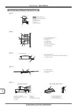
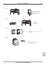
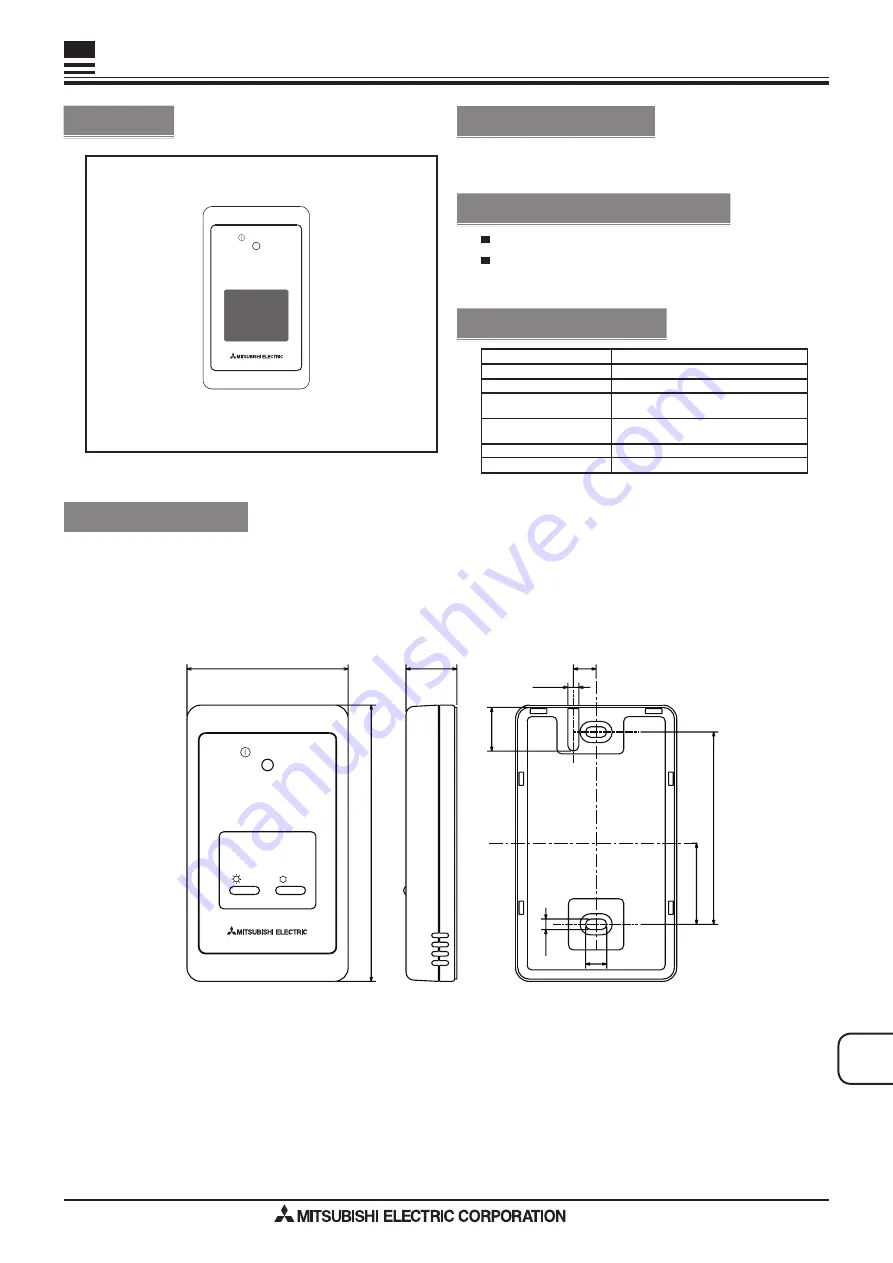
Figure
Specifications
SEZ-KD
**N
A
PEA-
A**A
A
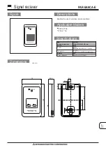
Signel reciever
PAR-SA9CA-E
Unit : mm
Descriptions
Applicable Models
Dimensions
ON/OFF
120(H)×70(W)×22.5(D) mm
external dimensions
Content
Item
DC12V
(supplied from indoor unit control)
Power
Tempreture
0
~
40
℃
Humidity : 30
~
90%RH (no condensing)
Colour (Munsell)
White Grey (4.8Y7.92/0.66)
Material
ABS
0.2kg
Weight
9.9
83.5
19
4.8
35.2
9.2
4.6
22.5
120
70
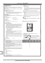
ON/OFF
COOL
HEAT


