OPERATING PROCEDURE
PHOTOS
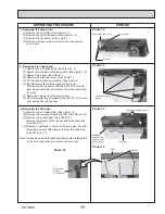
10. Removing the pipe temperature thermistor/liquid (TH2)
and the condenser/evaporator temperature thermistor
(TH5)
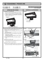
(1) Remove the air intake grille. (See Figure 1, 2)
(2) Remove the left and right side panels. (See Figure 3, 4)
(3) Remove the under panel. (See Photo 13)
(4) Remove the drain pan. (See Photo 14, 15, 16)
(5) Disconnect the connector CN44 (white) from the indoor
controller board.
(6) Remove 6 screws from the pipe cover and remove the
pipe cover. (See Photo 14, 17)
(7) Remove the fastener for wires and remove the thermistors
(TH2 and TH5) from each holder. (See Photo 18)
Photo 17
Condenser/evaporator
temperature thermistor
(TH5)
Pipe cover
Pipe cover fixing
screws
Pipe cover
fixing screws
(See Photo 15)
Fastener
Photo 18
Pipe tempera-
ture thermistor/
liquid (TH2)
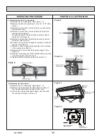
12. Removing the Auto vane
(1) Remove the intake grille. (See Figure 1, 2)
(2) Remove the right side panel. (See Figure 3, 4)
(3) Remove the vane motor and cover. (See Photo 12)
(4) Slide the auto vane to the vane motor side.
(5) Remove 2 axes from each vane support pushing the
vane support to the vane sleeve side.
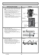
11. Removing the guide vane
(1) Remove the intake grille. (See Figure 1, 2)
(2) Remove the side panel (right and left). (See Figure 3, 4)
(3) Remove the under panel. (See Photo 13)
(4) Remove the drain pan. (See Photo 14, 15, 16)
(5) Remove the screw from the guide vane, then remove
the guide vane.
Photo 19
Screw
Guide vane
Drain pan
Photo 20
Vane support
Vane
Vane sleeve
Vane motor side
40
OCH638

