background image

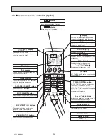
Setting and display items

Setting details

Vane · Louver · Vent. (Lossnay)

Use to set the vane angle.

‡

 Select a desired vane setting from 

 different settings.

Use to turn ON/OFF the louver.

‡

 Select a desired setting from 

ON

 and 

OFF.

Use to set the amount of ventilation.

‡

 Select a desired setting from 

Off,


Low,

 and 

High.

High power**

Use to reach the comfortable room temperature quickly.

‡

 Units can be operated in the High-power mode for up to 30 minutes.

Timer

ON/OFF timer*

Use to set the operation ON/OFF times.

‡

 Time can be set in 

-minute increments.

Auto-OFF timer

Use to set the Auto-OFF time.

‡

 Time can be set to a value from 30 to 240 in 10-minute increments.

Weekly timer*

Use to set the weekly operation ON/OFF times.

‡

 Up to 

 operation patterns can be set for each day. (Not valid when the ON

OFF timer is enabled.)

Restriction

Temp. range

Use to restrict the preset temperature range.

‡

 Different temperature ranges can be set for different operation modes.

Operation lock

Use to lock selected functions.

‡

 The locked functions cannot be operated.

Energy saving

Auto return

Use to get the units to operate at the preset temperature after performing energy-save operation for a 
speci ed time period.

‡

 Time can be set to a value from 30 and 120 in 10-minute increments.

(This function will not be valid when the preset temperature ranges are restricted.)

Schedule*

Set the start/stop times to operate the units in the energy-save mode for each day of the week, and set the 
energy-saving rate.

‡

 Up to 4 energy-save operation patterns can be set for each day.

‡

 Time can be set in 

-minute increments.

‡

 Energy-saving rate can be set to a value from 0

 or 

0 to 

0

 in 10

 increments.

Night setback*

Use to make Night setback settings.

‡

 Select 

Yes

 to enable the setting, and 

No

 to disable the setting. The temperature range and the start

stop times can be set.

Filter information

Use to check the  lter status.

‡

 The 

¿

lter sign can be reset.

Error information

Use to check error information when an error occurs.

‡

 Check code, error source, refrigerant address, unit model, manufacturing number, contact information (dealer

phone number) can be displayed.

(The unit model, manufacturing number, and contact information need to be registered in advance to be displayed.)

Maintenance

Manual vane angle**

Use to set the vane angle for each vane to a  xed position.

3D i-see Sensor

Use to set the following functions for 3D i-see Sensor.


‡

 Air distribution 

‡

 Energy saving option 

‡

 Seasonal air

À

ow

Initial setting

Main/Sub

When connecting 2 remote controllers, one of them needs to be designated as a sub controller.

Clock

Use to set the current time.

Main display

Use to switch between "Full" and "Basic" modes for the Main display.

‡

 The initial setting is 

Full.

Contrast

Use to adjust screen contrast.

Display details

Make the settings for the remote controller related items as necessary.
Clock: 

The initial settings are 

Yes

 and 

24h

 format.

Temperature: 

Set either Celsius (

ƒ

C) or Fahrenheit (

ƒ

F).

Room temp. : 

Set Show or Hide.

Auto mode: 

Set the Auto mode display or Only Auto display.

Auto mode

Whether or not to use the Auto mode can be selected by using the button.
This setting is valid only when indoor units with the Auto mode function are connected.

Administrator password

The administrator password is required to make the settings for the following items.

‡

 Timer setting  

‡

 Energy-save setting  

‡

 Weekly timer setting

‡

 Restriction setting  

‡

 Outdoor unit silent mode setting  

‡

 Night set back 

Language selection

Use to select the desired language.

Service

Test run

Select "Test run" from the Service menu to bring up the Test run menu.

‡

 Test run  

‡

 Drain pump test run

Input maintenance

Select "Input maintenance Info." from the Service menu to bring up the Maintenance information screen.
The following settings can be made from the Maintenance Information screen.

‡


0

odel name input   

‡

 Serial No. input   

‡

 Dealer information input

Function setting

Make the settings for the indoor unit functions via the remote controller as necessary.

Check

Error history: 

Display the error history and execute 

³

delete error history

´

.

Refrigerant leak check: 

Refrigerant leaks can be judged.

Smooth maintenance: 

The indoor and outdoor maintenance data can be displayed.

Request code: 

Details of the operation data including each thermistor temperature and error history can be checked.

Self check

Error history of each unit can be checked via the remote controller.

Maintenance password Use to change the maintenance password.
Remote controller check When the remote controller does not work properly, use the remote controller checking function to trouble-

shoot the problem.

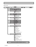
Main menu list

 Clock setting is required.

 The function is not available for 

0;=

 model.

OCH638

Summary of Contents for PCA-A24KA7

Page 1: ... SPECIAL FUNCTION 32 12 DISASSEMBLY PROCEDURE 36 COOL DRY AUTO FAN HEAT Notes TKLs PDQXDO GesFULEes oQO seUYLFe GDtD oI tKe LQGooU XQLts RoH6 FoPSOLDQt SUoGXFts KDYe PDUN oQ tKe sSeF QDPe SODte PARTS CATALOG OCB638 0oGeO QDPe LQGLFDtLoQ WIRED REMOTE CONTROLLER Option IR WIRELESS REMOTE CONTROLLER Option Indoor unit Model Name Service Ref PCA A24KA7 PCA A24KA7 TH PCA A30KA7 PCA A30KA7 TH PCA A36KA7...

Page 2: ...O No 3U A2 3 NHA 3U A3 2N A 3U A2 3 NHA 6 3U A3 2N A 6 3U A2 3 NHA 3U A3 2N A 3U A2 3 NHA 6 3U A3 2N A 6 OCH 3 OC 3 3UY A2 3 NHA 3UY A3 2N A 3UY A2 3 NHA 6 3UY A3 2N A 6 3UY A2 3 NHA 3UY A3 2N A 3UY A2 3 NHA 6 3UY A3 2N A 6 3U HA3 3 NHA 3U HA3 3 NHA OCH OC 3U HA 2N A 3U HA 2N A OCH OC 0 3C2 NAH 2 0 3C2 NAH 2 U O H 2 O 2 0 C3 NA2 0 C 2NA2 0 C3 NA2 U 0 C 2NA2 U 0 3C3 NAH 2 0 3C3 NAH 2 U OCH638 ...

Page 3: ...rigerant oil etc If large amount of mineral oil enters that can cause deterio ration of refrigerant oil etc The refrigerant oil applied to flare and flange connections must be ester oil ether oil or alkylbenzene oil in a small amount Make sure that the inside and outside of refrige rant piping is clean and it has no contaminants such as sulfur oxides dirt shaving particles etc which are hazards to...

Page 4: ... 03a G or over 2 Charge hose  Only for R410A  Use pressure performance of 3 2 3SIG 0 03a G or over 3 Electronic scale 4 Gas leak detector  Use the detector for R134a R40 C or R410A 5 Adaptor for reverse flow check  Attach on vacuum pump 6 Refrigerant charge base 7 Refrigerant cylinder  Only for R410A  Top of cylinder 3ink  Cylinder with syphon 8 Refrigerant recovery equipment 1 Cautions for...

Page 5: ...previous screen ű4 MENU button Press to bring up the Main menu ű5 Backlit LCD Operation settings will appear When the backlight is off pressing any button turns the backlight on and it will stay lit for a certain period of time depending on the screen When the backlight is off pressing any button turns the backlight on and does not perform its function except for the ON OFF button ű6 ON OFF lamp T...

Page 6: ...l ű Indicates the ventilation setting ű Appears when the preset temperature range is restricted ű1 Operation mode Indoor unit operation mode appears here ű2 Preset temperature Preset temperature appears here ű3 Clock See the Installation Manual Current time appears here ű4 Fan speed Fan speed setting appears here ű5 Button function guide Functions of the corresponding buttons appear here ű6 Appear...

Page 7: ...nt Lossnay High power Weekly timer Restriction Maintenance Initial setting ON OFF timer Auto OFF timer Temp range Operation lock Manual vane angle Main Sub Timer Main display Contrast Display details Auto mode Administrator password Language selection Service Input maintenance info Function setting Check Self check Maintenance password Remote controller check Test run Clock Menu structure Filter I...

Page 8: ...nce Manual vane angle Use to set the vane angle for each vane to a xed position 3D i see Sensor Use to set the following functions for 3D i see Sensor Air distribution Energy saving option Seasonal airÀow Initial setting Main Sub When connecting 2 remote controllers one of them needs to be designated as a sub controller Clock Use to set the current time Main display Use to switch between Full and ...

Page 9: ...he order of timer operation display Displays whether timer is on or off Buttons used to set the hour and minute of the current time and timer settings h and min buttons display display FAN SPEED display indicates which fan speed has been selected display The vertical direction of air flow is indicated display Blinks when model is selected display display CHECK and TEST RUN display indicate that th...

Page 10: ... Service Ref Power supply phase cycle voltage Max Fuse Size Min Circuit Ampacity External finish Heat exchanger Fan Fan drive o No Fan motor output Fan motor Airflow Low Medium2 Medium1 High External static pressure Operation control Thermostat Noise level Low Medium2 Medium1 High Field drain pipe O D Dimensions Weight W D H PCA A30KA7 TH INDOOR UNIT Pa mmAq inch mm inch mm inch mm inch mm lb kg C...

Page 11: ... Ref Power supply phase cycle voltage Max Fuse Size Min Circuit Ampacity External finish Heat exchanger Fan Fan drive o No Fan motor output Fan motor Airflow Low Medium2 Medium1 High External static pressure Operation control Thermostat Noise level Low Medium2 Medium1 High Field drain pipe O D Dimensions Weight W D H PCA A42KA7 TH INDOOR UNIT Pa mmAq inch mm inch mm inch mm inch mm lb kg CFM K min...

Page 12: ...NOTCH High Medium1 Medium2 Low SPL dB 41 39 37 35 LINE 90 80 70 60 50 40 30 20 10 63 125 250 500 1000 2000 4000 8000 APPROXIMATE THRESHOLD OF HEARING FOR CONTINUOUS NOISE NC 60 NC 50 NC 40 NC 30 NC 20 NC 70 BAND CENTER FREQUENCIES Hz OCTAVE BAND SOUND PRESSURE LEVEL dB 0 dB 0 0002 μbar NOTCH High Medium1 Medium2 Low SPL dB 43 41 39 37 LINE 90 80 70 60 50 40 30 20 10 63 125 250 500 1000 2000 4000 8...

Page 13: ...233 2 127 6 8VH 0 RU VFUHZ IRU DQFKRU EROW 3OHDVH EH VXUH ZKHQ LQVWDOOLQJ WKH GUDLQ SXPS RSWLRQ SDUWV UHIULJHUDQW SLSH ZLOO EH RQO XSZDUG 5267 67 1 ODPS PHUJHQF RSHUDWLRQ VZLWFK RROLQJ 5HFHLYHU 2SHUDWLRQ ODPS PHUJHQF RSHUDWLRQ VZLWFK HDWLQJ Q FDVH RI ZLUHOHVV UHPRWH FRQWUROOHU DQG L VHH 6HQVRU 2SWLRQDO 3DUWV QRFNRXW KROH IRU XSSHU GUDLQ SLSH DUUDQJHPHQW QRFNRXW KROH IRU IUHVK DLU LQWDNH ĭ ĭ QRFNRX...

Page 14: ...7 1 2 190 1 16 1 10 1 4 260 1 16 2 When electrical box is pulled down 2 15 16 75 2 1 1 2 38 7 4 3 3 8 85 3 3 8 86 15 1 4 387 2 Electrical box Air intake 59 3 4 1518 26 3 4 680 18 3 4 476 57 182 85 7 3 16 3 3 8 2 1 4 In case of wireless remote controller and i see sensor Optional Parts Emergency operation switch Heating Operation lamp Receiver Emergency operation switch Cooling DEFROST STAND BY lam...

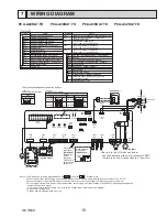
Page 15: ... MOTOR DRAIN PUMP DRAIN FLOAT SWITCH TERMINAL BLOCK INDOOR OUTDOOR CONNECTING LINE TERMINAL BLOCK REMOTE CONTROLLER TRANSMISSION LINE ROOM TEMP THERMISTOR Nȍ Nȍ 7 7 PIPE TEMP THERMISTOR LIQUID Nȍ Nȍ 7 7 COND EVA TEMP THERMISTOR Nȍ Nȍ 7 7 MF FUSE MV DP CN2L CONNECTOR BACK UP HEATING CN24 FS CN32 CN41 CN51 TB4 LED1 TB5 LED2 TH1 LED3 X1 TH2 SW1 TH5 SW2 SWE 1 6 PER V XVHG LQ ZLULQJ GLDJUDP DERYH DUH R...

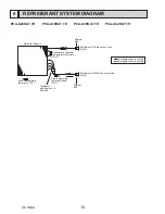
Page 16: ...thermistor TH5 Room temperature thermistor TH1 Refrigerant flow in cooling Refrigerant flow in heating Strainer 50 Strainer 50 Heat exchanger Refrigerant GAS pipe connection Flare Refrigerant LIQUID pipe connection Flare REFRIGERANT SYSTEM DIAGRAM 8 PCA A24KA7 TH PCA A30KA7 TH PCA A36KA7 TH PCA A42KA7 TH OCH638 ...

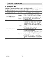
Page 17: ... of the trouble according to 9 4 TROUBLESHOOTING BY INFERIOR PHENOMENA The trouble is not reoccurring Logged Not logged 1Consider the temporary defects such as the work of protection devices in the refrigerant circuit including compressor poor connection of wiring noise etc Re check the symptom and check the installation environment refrigerant amount weather when the trouble occurred matters rela...

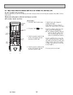
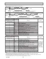
Page 18: ...e of trouble during operation When a malfunction occurs to air conditioner both indoor unit and outdoor unit will stop and operation lamp blinks to inform unusual stop CHECK lights and refrigerant address 00 blinks Check that the remote controller s display has stopped before continuing Select the refrigerant address of the indoor unit for the self diagnosis Note Set refrigerant address using the ...

Page 19: ...ler Beeper sounds OPERATION INDICATOR lamp blinks Check code Number of times IR wireless remote controller Wired remote controller 1 P1 Intake sensor error P9 Pipe TH5 sensor error 2 P2 Pipe TH2 sensor error 3 E6 E7 Indoor outdoor unit communication error 4 P4 Float switch connector CN4F open 5 P5 PA Drain pump error Forced compressor stop due to water leakage abnormality 6 P6 Freezing Overheating...

Page 20: ...ed Reverse or open phase wiring for the outdoor unit s power terminal block L1 L2 GR Incorrect wiring between indoor and outdoor units incorrect polarity of S1 S2 S3 Remote controller wire short Note Operation is not possible for about 30 seconds after cancellation of function selection Correct operation For description of each LED LED1 2 3 provided on the indoor controller refer to the following ...

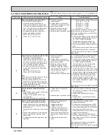
Page 21: ...ermistor wiring 4 Defective refrigerant circuit is causing thermistor temperature of 194 F 90 or more or í40 F í40 or less 5 Defective indoor controller board 1 3 Check resistance value of thermistor For characteristics refer to P1 above 2 Check contact failure of connector CN44 on the indoor controller board Refer to 9 7 TEST POINT DIAGRAM Turn the power on and check restart after inserting conne...

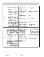
Page 22: ...ck operating condition of refriger ant circuit Heating mode 1 Check clogs of the filter 2 Remove shields 4 Refer to 9 6 HOW TO CHECK THE PARTS 5 Check outdoor fan motor 6 8Check operating condition of refriger ant circuit P8 Pipe temperature Cooling mode Detected as abnormal when the pipe tem perature is not in the cooling range 3 min utes after compressor start and 6 minutes after the liquid or c...

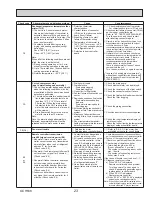
Page 23: ...4 Contact failure of float switch con nector 5 Dew condensation on float switch  Drain water descends along lead wire  Drain water is waving due to filter clogging 6 Extension piping connection dif ference at twin triple or quadruple system 7 Miswiring of indoor outdoor con necting at twin triple or quadruple system 8 Room temperature thermistor liquid pipe temperature thermistor detection is de...

Page 24: ...red into indoor outdoor unit connecting wire Check LED display on the outdoor control circuit board Connect A control service tool PAC SK52ST Refer to outdoor unit service manual 1 Check disconnection or looseness of indoor outdoor unit connecting wire of indoor unit or outdoor unit Check all the units in case of twin triple indoor unit system 2 4 Turn the power off and on again to check If abnorm...

Page 25: ...tor Normal operation Each connector on vane motor side is disconnected or set ting the fixed vanes by wired remote controller Phenomena Cause Countermeasure 2 Receiver for IR wireless remote controller Weak batteries of IR wireless remote controller Contact failure of connector CNB on IR wireless remote controller board Insert failure Contact failure of connector CN90 on indoor con troller board I...

Page 26: ...control When the remote control does not function it is possible to activate Emergency Operation by using the indoor unit Emergency Operation switch SW1 SW2 of the IR wireless signalreceiver board However if the indoor unit microprocessor has failed it is necessary to proceed with points 2 and 3 below as in the case of the wired remote controller 2 When you activate Emergency Operation of the cool...

Page 27: ... for i see Sensor Option Abnormal Open or short Red Yellow Red Blue Red Orange Red White Connector Normal Measure the resistance between the terminals with a tester At the ambient temperature of 68 to 86Û WR Û Abnormal Open or short Red Yellow Red Blue Red Orange Red White Connector Normal Normal 7XUQ RQ WKH LQGRRU XQLW ZLWK WKH EODFN SODVWLF WDSH RQ WKH RXWVLGH RI L VHH 6HQVRU FRQWUROOHU ERDUG i ...

Page 28: ...e No 1 2 Yes No Check the operation of fan END Yes OK Check the operation END OK Check method of DC fan motor fan motor indoor controller circuit board Sensor signal check Measure the voltage between CNMF 7 and 4 0 and 15 V DC in the indoor controller circuit board Does the voltage repeat 0 and 15 V DC No Yes Indoor controller board fuse check Is the fuse blown Replace the indoor controller board ...

Page 29: ...p output DP 208 230 V AC option CN01 Connect to the Terminal Block TB4 Indoor outdoor connecting line Between 3 and 5 208 230 V AC CNV Vane motor output MV 12 V pulse output SWE Emergency operation Jumper wire J41 J42 Pair No setting for IR wireless remote controller FUSE 6 3 A 250 V CNMF Fan motor 1 4 294 325 V DC 5 4 15 V DC VCC Voltage between pins of C955 15 V DC Same as 5 4 í of CNMF CN44 Pip...

Page 30: ...1 J42 are given in the table on the left in the table indicates the jumper line is disco nnected There is no jumper JP1 because these models have the cond eva temperature thermistor TH5 Jumper wire Short Open Without TH5 With TH5 Model JP1 For product Spare parts Indoor controller board type JP3 with JP3 without JP3 Service board MODEL PCA A24KA7 1 2 3 4 5 1 2 3 4 5 1 2 3 4 5 ON OFF PCA A30KA7 ON ...

Page 31: ...to 00 Refer to the service manual that comes with each outdoor unit 2 Functions available when setting the unit number to 01 03 or AL 07 in case of wireless remote controller Function Settings Mode No Setting No Initial setting Setting Filter sign 100 Hr 07 1 2500 Hr 2 ż No lter sign indicator 3 Fan speed Silent 08 1 Standard 2 ż High ceiling 3 Up down vane setting No vanes 11 1 Equipped with vane...

Page 32: ... and Back up function Outline of functions  Main and sub units operate alternately according to the interval of rotation setting Note Main and sub unit should be set by refrigerant address Outdoor DIP switch setting Refrigerant address 00 Main unit Refrigerant address 01 Sub unit  When error occurs to one unit another unit will start operation Back up function System constraint  This function i...

Page 33: ...5day and back up function No 7 316 Rotation ON Alternating interval 7day and back up function No 8 317 Rotation ON Alternating interval 14day and back up function No 9 318 Rotation ON Alternating interval 28day and back up function 1 Request Code List Rotation setting 2nd stage cut in setting Ex Set temp by R C 68 F 20 Set point 79 F 26 When request code number is 323 79 F 2nd unit Cut in 7 2 F 71...

Page 34: ...e with the F1 or F2 button Set each number 0 through 9 with the F3 or F4 button Note The initial maintenance password is 9999 4 Then press the button 5 Select Check with the F1 or F2 button and press the button 6 Select Request code with the F1 or F2 button and press the button 7 Set the Refrigerant address and Request code Select the item to be changed with the F1 or F2 button Select the required...

Page 35: ... change the heater ON delay time You can set these function by wired remote controller Note that the change can be made only by the wired remote controller PAR 32MAA Notes 1 Both main and sub unit should be set in the same setting 2 Every time replacing indoor controller board for serving the function should be set again 3 Stop the air conditioner operation before changing the heater ON delay time...

Page 36: ...ctrical cover and remove the electrical cover 4 Remove 2 screws from the electrical box and pull the electrical box downward Temporarily secure the electrical box using 2 hooks in the back of electrical box 5 Disconnect the connectors on the indoor controller board Removing the electrical box 6 Disconnect the wires from the terminal blocks and pull out the electrical box See Photo 2 Removing the i...

Page 37: ... 4 î 8 PT See Photo 1 3 Remove 2 screws from the electrical cover and remove the electrical cover 4 Remove 2 screws from the electrical box and pull the electrical box downward 5 Temporarily secure the electrical box using 2 hooks in the back of electrical box 6 Remove the lower casing while pressing the 4 catches of the casing right side of the fan motor See Photo 6 7 Loosen the 2 set screws 2 he...

Page 38: ...ver 4 Remove 2 screws from the electrical box and pull the electrical box downward Temporarily secure the electrical box using 2 hooks in the back of electrical box 5 Remove 2 screws from the left side beam and remove the beam See Photo 9 6 Loosen 2 set screws 2 hexagon set screws of connect ing joint See Photo 5 7 Remove 3 lower casings while pressing each 4 catches of the casing See Photo 6 8 Re...

Page 39: ...ght side panel See Figure 3 4 3 Remove the connector of vane motor 4 Remove 2 screws of vane motor cover then remove vane motor Photo 12 Screws Connector Vane motor and cover Photo 13 Under panel fixing screws 9 Removing the drain pan 1 Remove the air intake grille See Figure 1 2 2 Remove the side panel right and left See Figure 3 4 3 Remove the under panel See Photo 13 Remove the screws of the ri...

Page 40: ...re thermistor TH5 Pipe cover Pipe cover fixing screws Pipe cover fixing screws See Photo 15 Fastener Photo 18 Pipe tempera ture thermistor liquid TH2 12 Removing the Auto vane 1 Remove the intake grille See Figure 1 2 2 Remove the right side panel See Figure 3 4 3 Remove the vane motor and cover See Photo 12 4 Slide the auto vane to the vane motor side 5 Remove 2 axes from each vane support pushin...

Page 41: ...ipe thermistors TH2 and TH5 from each holder See Photo 18 7 Remove the pipe band fixing screw and remove the pipe band See Photo 21 8 Remove 3 screws from the heat exchanger and remove the heat exchanger See Photo 22 Caution To avoid falling of the heat exchanger be sure to hold the heat exchanger by hand For safety reasons this procedure must be performed by two persons Photo 21 Pipe band fixing ...

Page 42: ...ht 2016 MITSUBISHI ELECTRIC CORPORATION Published Oct 2016 No OCH638 Made in Japan HEAD OFFICE TOKYO BUILDING 2 7 3 MARUNOUCHI CHIYODA KU TOKYO 100 8310 JAPAN Specifications are subject to change without notice ...

Reviews: