25
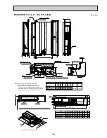
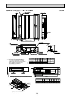
Unit : mm
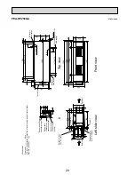
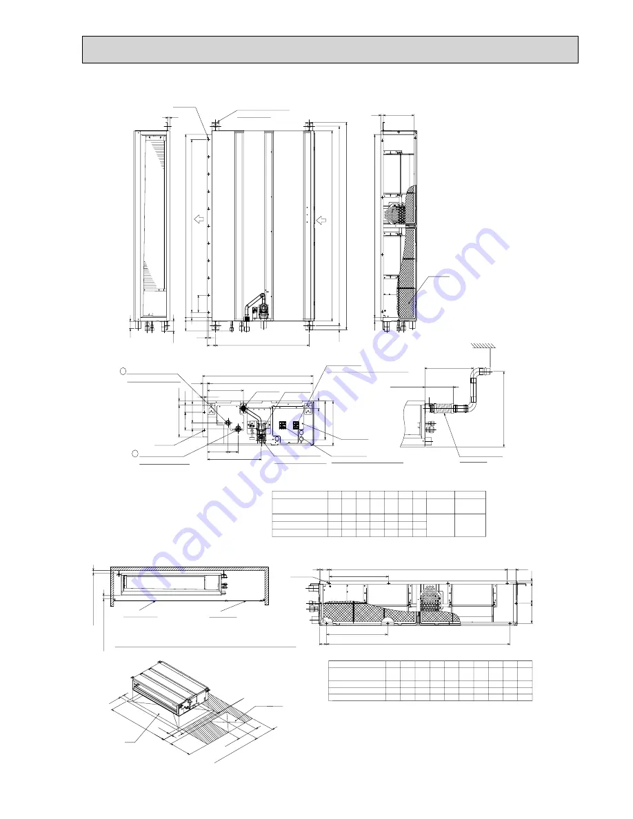
PEAD-RP35, 50, 60, 71, 100, 125, 140JA
Air Filter
Suspension bolt hole
4-14x30 Slot
Air
outlet
Air
inlet
2xE-
:
2.9
2×2-
:
2.9
Refrigerant piping
Flare connection (liquid)
2
1 Refrigerant piping
Flare connection (gas)
Drain pump
Control box
Terminal block
(Indoor/Outdoor connecting line)
Terminal block
(Remote controller transmission line)
Drain pipe(O.D.
:
32)
(Spontaneous draining)
Drain pipe
(O.D.
:
32)
:
15.88
:
9.52
:
6.35
:
12.7
Liquid pipe
Gas pipe
1558
1358
1500
1300
Model
A
1200
900
954
860
9
E
11
D
1060
C
1100
B
1154
PEAD-RP140JA
PEAD-RP100,125JA
PEAD-RP60,71JA
PEAD-RP35,50JA
1400
1600
1454
1654
1500
1700
1360
1560
14
16
1000
1000
F
858
800
G
1058
40
210
18
G
21
250
122
33
15
58
57
10
100
100x(E-1)=F
A
B(Suspension bolt pitch)
C
23
643 (Suspension bolt pitch)
30
57
20
D (Duct)
178
(Duct)
40
23
10
238
32
700
732
136
67
356
100
41
217
NOTE 1. Use M10 screw for the Suspension bolt (field supply).
2. Keep the service space for the maintenance at the bottom.
3. This chart indicates for PEAD-RP60
•71•100•125•140JA
models,which have 2 fans. PEAD-RP35
•50JA models have 1 fan.
4. In case that the inlet duct is used, remove the air filter (supplied with
the unit), then install the filter (field supply) at suction side.
Less than 300mm
175±5mm
Less than 700mm
Drain hose (I.D.
:
32)
<accessory>
(Actual length)
1520
1320
1020
819
J
Q
S
340
R
54
260
4
780
10
40.5
273
4
4
40
P
10
N
990
M
4
L
49
K
330
5
5
380
54
54
320
370
5
5
1280
1480
12
12
40
40
330
1700
1500
PEAD-RP35,50JA
PEAD-RP60,71JA
PEAD-RP100,125JA
PEAD-RP140JA
1200
1000
H
Model
N-
:
2.9
K
Kx(L-1)=M
J
11
2
11
2
11
Q
Qx(R-1)=S
P
J
6
More than 20mm
More than 10mm
Make the access door at the appointed position properly for service maintenance.
Ceiling surface
Access door
50
250~300
450
50
H
777
450
More than 300
Access door
Note2
Required space for service and maintenance

