background image

28

Unit : mm

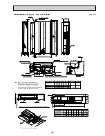
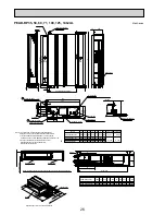
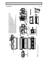
PEA-RP250GA

Rubber bush <Remote

controller wiring>

Rubber bush

<Outdoor unit

connection wiring>

Rubber bush

<Power supply

wiring>

 A 

A

4-

:

12

Drain R1

T

op view

Control box

22-

:

3.1

<For hanging bolt M10>

[Field supply]

Return air

duct flange

Supply air

duct flange

26-

:

3 Holes

Left side view

Supply air

Return air

Front view

Return air

sensor

<Accessory>

Pipe cover··················2pcs.

(For dew condensation prevention of local piping and unit connection)

Remote controller·······1pc.

Refrigerant pipe

:

12.7 (1/2 braze)

Refrigerant pipe

:

25.4 (1 braze)

42

144

145

75

55

70

129

124

131

50

530

34

130

95

250

11

10

66

1302

1484

7x130(=910)

130

45

45

200

20

100

20

199

40

1500

462

66

9X130(=1

170)

10

25

100100

25

10

10

1540

40

1460

40

255

205

376

1000

1600

73

262

400

39

565

54

634

35

130

89

330

22

130

35

Summary of Contents for PKA-RP HAL

Page 1: ...ABLE EXTENSION PIPE FOR EACH MODEL 66 9 AIR FLOW DATA 75 10 NOISE CRITERION CURVES 90 11 OPTIONAL PARTS 106 Indoor unit Model names R410A PLA RP BA BA2 BA3 PEAD RP JA L PEA RP GA PKA RP HAL PKA RP KAL PCA RP KA PCA RP HA PSA RP GA Outdoor unit Model names SPLIT TYPE HEAT PUMP AIR CONDITIONERS PUHZ RP35 50 60 71VHA4 PUHZ RP100 125 140VKA PUHZ RP100 125 140YKA PUHZ RP200 250YKA July 2009 INVERTER kW...

Page 2: ...A RP71 125HA PCA RP71 125HA 1 OC329 PKA RP35 50HAL PKA RP35 50HAL OCH453 OCB453 PKA RP60 71 100KAL PKA RP60 71 100KAL TH OCH452 OCB452 PSA RP71 100 125 140GA PSA RP71 100 125 140GA 1 OC332 PEAD RP35 50 60 71 100 125 140JA L PEAD RP35 50 60 71 100 125 140JA L UK HWE08130 BWE08240 PEA RP200 250 400 500GA PEA RP200 250 400 500GA TH AF PEA RP200 250GA TH AFMF HWE0708A 1 2 OUTDOOR UNIT Model name Servi...

Page 3: ...Panel lbs 49 13 Field drain pipe O D mm 32 inch 1 1 4 Outdoor unit Air flow CMM 35 CFM 1 240 Sound level at cooling dB A 44 Sound level at heating dB A 46 External finish Ivory Munsell 3Y 7 8 1 1 Dimension W mm 800 D mm 300 23 H mm 600 W inch 31 1 2 D inch 11 13 16 7 8 H inch 23 5 8 Weight kg 42 lbs 93 Refrigerant pipe size Gas side O D mm 12 7 inch 1 2 Liquid side O D mm 6 35 inch 1 4 Refrigerant...

Page 4: ...drain pipe O D mm 32 inch 1 1 4 Outdoor unit Air flow CMM 60 CFM 2 120 Sound level at cooling dB A 47 Sound level at heating dB A 48 External finish Ivory Munsell 3Y 7 8 1 1 Dimension W mm 950 D mm 330 30 H mm 943 W inch 37 3 8 D inch 13 1 3 16 H inch 37 1 8 Weight kg 67 lbs 148 Refrigerant pipe size Gas side O D mm 15 88 inch 5 8 Liquid side O D mm 9 52 inch 3 8 Refrigerant pipe length Height dif...

Page 5: ...LA RP100BA PUHZ RP100VKA 34 100 10 0 4 9 11 4 2 65 3 77 0 74 38 200 11 2 4 5 14 0 2 79 4 01 4 61 Energy label class A Booster heater kW A Power supply Phase 1 Cycle Hz 50 Voltage V 230 Breaker size A 32 25 23 6 51 13 25 6 55 13 26 6 57 13 Indoor unit Air flow CMM 14 16 18 21 Low Medium2 Medium1 High CFM 495 565 635 740 External pressure Pa 0 Sound level dB A 28 30 32 34 20 23 26 30 710 810 920 106...

Page 6: ... 54 600 kW 14 0 5 0 16 0 14 0 5 0 16 0 16 0 5 7 18 0 Total input kW 3 86 3 50 4 32 COP 3 63 4 00 3 70 Energy label class A A Booster heater kW Power supply Phase 1 Cycle Hz 50 Voltage V 230 Breaker size A 32 25 6 55 13 27 6 60 13 40 Indoor unit Air flow CMM 22 25 28 31 22 25 28 31 Low Medium2 Medium1 High CFM 780 880 990 1090 780 880 990 1090 External pressure Pa 0 0 Sound level dB A 34 36 39 41 3...

Page 7: ... O D mm 32 inch 1 1 4 Outdoor unit Air flow CMM 110 CFM 3 880 Sound level at cooling dB A 49 Sound level at heating dB A 51 External finish Ivory Munsell 3Y 7 8 1 1 Dimension W mm 1 050 D mm 330 30 H mm 1 338 W inch 41 5 16 D inch 13 1 3 16 H inch 52 11 16 Weight kg 124 lbs 273 Refrigerant pipe size Gas side O D mm 15 88 inch 5 8 Liquid side O D mm 9 52 inch 3 8 Refrigerant pipe length Height diff...

Page 8: ...14 0 6 2 15 3 3 83 3 67 4 36 3 26 3 41 3 21 A A 0 71 0 71 0 71 47 800 47 800 54 600 14 0 5 0 16 0 14 0 5 0 16 0 16 0 5 7 18 0 3 86 3 50 4 32 3 63 4 00 3 70 A A 25 6 55 13 27 6 60 13 22 25 28 31 22 25 28 31 780 880 990 1090 780 880 990 1090 0 0 34 36 39 41 34 36 39 41 24 26 29 32 850 920 1020 1130 0 36 39 42 44 White Munsell 6 4Y 8 9 0 4 840 950 840 950 298 35 33 1 16 37 3 8 33 1 16 37 3 8 11 3 4 1...

Page 9: ...gy label class A A SHF 0 85 0 84 Heating Capacity Btu h 14 000 20 500 kW 4 1 1 6 5 2 6 0 2 5 7 3 Total input kW 1 10 1 56 COP 3 73 3 85 Energy label class A A Booster heater kW Power supply Phase 1 Cycle Hz 50 Voltage V 230 Breaker size A 16 Indoor unit Air flow CMM 10 12 14 Low Middle High CFM 353 424 494 External pressure Pa 35 50 70 100 150 Sound level dB A 23 27 30 Low Middle High 50Pa 12 14 5...

Page 10: ...3 Heating Capacity Btu h 23 900 27 300 kW 7 0 2 8 8 2 8 0 3 5 10 2 Total input kW 1 75 2 00 COP 4 00 4 00 Energy label class A A Booster heater kW Power supply Phase 1 Cycle Hz 50 Voltage V 230 Breaker size A 25 Indoor unit Air flow CMM 14 5 18 21 17 5 21 25 Low Middle High CFM 512 636 742 618 742 883 External pressure Pa 35 50 70 100 150 Sound level dB A 25 29 33 26 30 34 Low Middle High 50Pa Ext...

Page 11: ...4 0 83 Heating Capacity Btu h 38 200 47 800 54 600 kW 11 2 4 5 14 0 14 0 5 0 16 0 16 0 5 7 18 0 Total input kW 2 72 3 50 4 04 COP 4 12 4 00 3 96 Energy label class A A A Booster heater kW Power supply Phase 1 Cycle Hz 50 Voltage V 230 Breaker size A 32 40 Indoor unit Air flow CMM 24 29 34 32 39 46 Low Middle High CFM 847 1 024 1 201 29 5 35 5 42 1 042 1 253 1 483 1 130 1 377 1 624 External pressur...

Page 12: ...0 Voltage V 400 Breaker size A 16 Indoor unit Outdoor unit Weight kg 124 132 lbs 273 126 278 291 Refrigerant pipe size Gas side O D mm 15 88 inch 5 8 Liquid side O D mm 9 52 inch 3 8 Refrigerant pipe length Height difference m Max 30 Length m Max 75 34 100 42 700 47 800 10 0 4 9 11 4 12 5 5 5 14 0 14 0 6 2 15 3 2 77 2 75 3 86 3 84 4 36 4 34 3 61 3 64 3 24 3 26 3 21 3 23 A A A 0 82 0 84 0 83 38 200...

Page 13: ... 34 EER Energy label class 2 84 2 64 SHF 0 81 0 86 Heating Capacity Btu h 76 400 92 000 kW 22 4 9 5 25 0 27 0 12 5 31 5 Total input kW 6 50 8 20 COP 3 45 3 29 Energy label class Booster heater kW Power supply Phase 3 Cycle Hz 50 Voltage V 400 Breaker size A Indoor 15 Outdoor 32 Indoor unit Air flow CMM 52 65 64 80 Low High CFM 1835 2295 2260 2825 External pressure Pa 150 Sound level dB A 48 51 49 ...

Page 14: ...3 2 56 Energy label class Energy label class SHF 0 75 0 77 Heating Capacity Btu h 153 000 184 000 kW 44 8 18 0 50 0 54 0 25 0 63 0 Total input kW 12 55 16 88 COP 3 57 3 20 Booster heater kW Power supply Phase 3 Cycle Hz 50 Voltage V 400 Breaker size A Indoor 15 Outdoor 32 2 Indoor unit Air flow CMM 120 160 High CFM 4240 5650 External pressure Pa 150 Sound level dB A 52 53 High External finish Galv...

Page 15: ... 43 EER 3 67 3 22 Energy label class A A SHF 0 81 0 72 Heating Capacity Btu h 14 000 17 100 kW 4 1 1 6 5 2 5 0 2 5 7 3 Total input kW 1 13 1 38 COP 3 63 3 62 Energy label class A A Booster heater kW Power supply Phase 1 Cycle Hz 50 Voltage V 230 Breaker size A 16 Indoor unit Air flow CMM 9 10 5 12 Low Middle High CFM 320 370 425 External pressure Pa 0 Sound level dB A 36 40 43 Low Middle High Exte...

Page 16: ...ating Capacity Btu h 27 300 38 200 38 200 kW 8 0 3 5 10 2 11 2 4 5 14 0 11 2 4 5 14 0 Total input kW 2 13 3 10 3 10 COP 3 76 3 61 3 61 Energy label class A A A Booster heater kW Power supply Phase 1 Cycle Hz 50 Voltage V 230 Breaker size A 32 25 16 Indoor unit Air flow CMM 18 20 22 20 23 26 Low Middle High CFM 635 705 780 705 810 920 3 50 400 External pressure Pa 0 Sound level dB A 39 42 45 41 45 ...

Page 17: ...4 2 21 COP 3 61 3 62 Energy label class A A Booster heater kW Power supply Phase 1 Cycle Hz 50 Voltage V 230 Breaker size A 16 25 Indoor unit Air flow CMM 10 11 13 15 15 16 17 19 16 17 18 20 Low Medium2 Medium1 High CFM 355 390 460 530 530 565 600 670 565 600 635 705 External pressure Pa 0 Sound level dB A 32 34 37 40 33 35 37 40 35 37 39 41 Low Medium2 Medium1 High External finish White Munsell 6...

Page 18: ...ating Capacity Btu h 38 200 47 800 54 600 kW 11 2 4 5 14 0 14 0 5 0 16 0 16 0 5 7 18 0 Total input kW 3 02 3 88 4 43 COP 3 71 3 61 3 61 Energy label class A A A Booster heater kW Power supply Phase 1 Cycle Hz 50 Voltage V 230 Breaker size A 32 40 Indoor unit Air flow CMM 22 24 26 28 23 25 27 29 Low Medium2 Medium1 High CFM 775 850 920 990 810 885 955 1 025 24 26 29 32 850 920 1 025 1 130 External ...

Page 19: ...hase 3 Cycle Hz 50 Voltage V 400 16 Breaker size A Indoor unit Air flow CMM Low Medium2 Medium1 High CFM External pressure Pa Sound level dB A Low Medium2 Medium1 High External finish Dimension W mm D mm H mm W inch D inch H inch Weight kg lbs Field drain pipe O D mm inch Outdoor unit Air flow CMM CFM Sound level at cooling dB A Sound level at heating dB A External finish Dimension W mm D mm H mm ...

Page 20: ... level at cooling dB A 47 50 Sound level at heating dB A 48 52 External finish Ivory Munsell 3Y 7 8 1 1 Dimension W mm 950 1 050 D mm 330 30 330 30 H mm 943 1 338 W inch 37 3 8 41 5 16 D inch 13 1 3 16 13 1 3 16 H inch 37 1 8 52 11 16 Weight kg 67 116 126 lbs 148 256 278 Refrigerant pipe size Gas side O D mm 15 88 15 88 inch 5 8 5 8 Liquid side O D mm 9 52 9 52 inch 3 8 3 8 Refrigerant pipe length...

Page 21: ...W 2 20 EER 3 23 Energy label class A SHF 0 73 Heating Capacity Btu h 25 900 kW 7 6 3 5 10 2 Total input kW 2 23 COP 3 41 Energy label class B Booster heater kW Power supply Phase 1 Cycle Hz 50 Voltage V 230 Breaker size A 25 Indoor unit Air flow CMM 15 18 Low High CFM 530 635 External pressure Pa 0 Sound level dB A 40 45 Low High External finish White Munsell 0 70Y 8 59 0 97 Dimension W mm 600 D m...

Page 22: ...rgy label class A B C SHF 0 81 0 75 0 74 Heating Capacity Btu h 38 200 47 800 54 600 kW 11 2 4 5 14 0 14 0 5 0 16 0 16 0 5 7 18 0 Total input kW 3 28 4 11 4 97 COP 3 41 3 41 3 22 Energy label class B B C Booster heater kW Power supply Phase 1 Cycle Hz 50 Voltage V 230 Breaker size A 32 40 Indoor unit Air flow CMM 24 31 26 33 27 35 Low High CFM 850 1060 920 1165 955 1240 External pressure Pa 0 Soun...

Page 23: ...4 3 01 2 81 Energy label class A B C SHF 0 81 0 75 0 74 Heating Capacity Btu h 38 200 47 800 54 600 kW 11 2 4 5 14 0 14 0 5 0 16 0 16 0 5 7 18 0 Total input kW 3 28 4 11 4 97 COP 3 41 3 41 3 22 Energy label class B B C Booster heater kW Power supply Phase 3 Cycle Hz 50 Voltage V 400 Breaker size A 16 Indoor unit Air flow CMM 24 31 26 33 27 35 Low High CFM 850 1 060 920 1 165 955 1 240 External pre...

Page 24: ...it connecting terminal block Indoor power supply terminal block Option part Control wire entry Air intake hole Air intake hole Air outlet hole Air outlet hole Connected the attached flexible pipe or socket Keep approximately 10 to 15mm space between unit ceiling and ceiling slab Branch duct hole Fresh air intake hole Ceiling hole Suspension bolt pitch Suspension bolt pitch Remote controller termin...

Page 25: ...00 732 136 67 356 100 41 217 NOTE 1 Use M10 screw for the Suspension bolt field supply 2 Keep the service space for the maintenance at the bottom 3 This chart indicates for PEAD RP60 71 100 125 140JA models which have 2 fans PEAD RP35 50JA models have 1 fan 4 In case that the inlet duct is used remove the air filter supplied with the unit then install the filter field supply at suction side Less t...

Page 26: ... 10 N 990 M 4 L 49 K 330 5 5 380 54 54 320 370 5 5 1280 1480 12 12 40 40 330 1700 1500 PEAD RP35 50JAL PEAD RP60 71JAL PEAD RP100 125JAL PEAD RP140JAL 1200 1000 H Model N 2 9 K Kx L 1 M J 112 112 11 Q Qx R 1 S P J 6 More than 20mm More than 10mm Make the access door at the appointed position properly for service maintenance Ceiling surface Access door 50 250 300 450 50 H 777 450 More than 300 Acce...

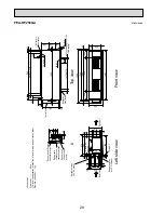
Page 27: ...4 3 Holes Refrigerant pipe 9 52 3 8 braze Refrigerant pipe 25 4 1 braze Accessory Pipe cover 2pcs For dew condensation prevention of local piping and unit connection Remote controller 1pc Return air Left side view Supply air Front view 75 55 129 70 42 124 34 131 530 50 95 250 11 7x130 910 10 130 130 45 45 31 31 1102 200 10 8x130 1040 1300 20 199 100 40 20 462 144 1284 400 155 1000 105 40 1260 40 1...

Page 28: ...e view Supply air Return air Front view Return air sensor Accessory Pipe cover 2pcs For dew condensation prevention of local piping and unit connection Remote controller 1pc Refrigerant pipe 12 7 1 2 braze Refrigerant pipe 25 4 1 braze 42 144 145 75 55 70 129 124 131 50 530 34 130 95 250 11 10 66 1302 1484 7x130 910 130 45 45 200 20 100 20 199 40 1500 462 66 9X130 1170 10 25 100 100 25 10 10 1540 ...

Page 29: ... flange Control box Supply air duct flange A Rubber bush Remote controller wiring Rubber bush Power supply wiring Rubber bush Outdoor unit connection wiring A Accessory Pipe cover 4pcs For dew condensation prevention of local piping and unit connection Remote controller 1pc 81 117 156 117 10 20 1840 10 40 60 60 61 60 40 40 1800 1880 50 664 525 22 102 22 5 120 4X120 480 22 5 595 1824 50 764 280 112...

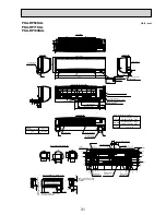
Page 30: ... for lower piping Louver manual Knockout hole for lower piping C 8 B Size Refrigerant pipe 6 35 Flared connection 1 4F Refrigerant pipe 12 7 Flared connection 1 2F 16 O D Liquid pipe Gas pipe Drain hose Knockout hole for right piping Right side Mount board 21 8 0 20 32 7 53 5 66 128 5 153 5 231 5 273 2 449 281 193 5 180 3 278 3 167 140 115 0 174 213 238 394 449 253 5 232 5 203 5 178 5 166 103 5 91...

Page 31: ...r unit Terminal block for power supply option Terminal block for MA remote controller option Emergency operation switch cooling heating Operation lamp DEFROST STAND BY lamp Receiver Knockout hole for right piping Mount board Right side 444 Gas pipe 482 Liquid pipe 585 Drain hose Filter hook Under side Vane auto Knockout hole for lower piping Louver manual Piping connection department Indoor unit o...

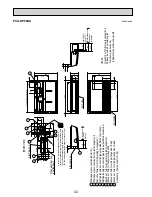
Page 32: ...26mmI D Drainage pipe connection for the left arrangement Knock out hole for left drain piping arrangement Refrigerant pipe connection gas pipe side flared connection Refrigerant pipe connection liquid pipe side flared connection 1 In case of the rear pipe arrangement make sure to remove the shaded portions from the independent piece Then put the independent piece back in initial position The heat...

Page 33: ... will be only upward Air outlet 233 Electrical box When electrical box is pulled down Electrical box 9 7 In case of the rear pipe arrangement make sure to remove the shaded portions from the independent piece Then put the independent piece back in initial position The heat exchanger might be clogged because of dust 5 10 51 246 A B 236 150 62 140 18 1237 Suspension bolt pitch 320 680 80 84 88 195 2...

Page 34: ...en electrical box is pulled down 2 NOTES 1 Use M10 or W3 8 screw for anchor bolt 2 Please be sure when installing the drain pump option parts refrigerant pipe will be only upward In case of the rear pipe arrangement make sure to remove the shaded portions from the independent piece Then put the independent piece back in initial position The heat exchanger might be clogged because of dust 5 10 51 2...

Page 35: ...justable part 288 360 Air outlet Suspension bolt pitch Air outlet Air intake Air intake Filter 3 pieces Terminal block box 5 2 1 4 3 Knockout hole for upper refrigerant pipe arrangement 6 9 2 1 Flexible hose accessory Drainage pipe connection 26mm I D Refrigerant pipe connection gas pipe side flared connection 5 8 inch 38 105 85 90 Electrical box Rear wall 500 250 2 3 Gap to ceiling Allowing clear...

Page 36: ...ing clearances Rear wall Gap to ceiling NOTES 1 Use M10 or W3 8 screw for anchor bolt Use the current nuts meeting the pipe size of the outdoor unit model PAC SG38KF E 12pcs Filter element for the exchange Suspension bolt pitch 122 246 handle 16 Flexible hose accessory Terminal block box 7 8 Filter contour dimension Inspection port pipe sensor The half bottom of FAN CASING can be separated Adjusta...

Page 37: ...ovided on both sides Knockout hole for piping and wiring 140 80 oval 20 105 Terminal block for indoor outdoor connection Electrical parts box Liquid pipe 9 52 3 8 inch 1 Service access allows for insertion of screw driver 2 Adjustable Gas pipe 15 88 5 8 inch Drain pipe Terminal block for heater power supply Only PSH P GAH 95 461 22 47 Front side Rear side Knockout hole for bottom fixing Knockout h...

Page 38: ...nockout hole for piping and wiring 140 80 oval 20 105 Electrical parts box Liquid pipe 9 52 3 8 inch 1 Service access allows for insertion of screw driver 2 Adjustable Gas pipe 15 88 5 8 inch Drain pipe 95 461 22 47 Front side Rear side Knockout hole for bottom fixing Knockout hole for under piping Knockout hole for under piping 120 70 oval 277 120 20 218 255 140 77 201 120 95 40 66 261 100 or mor...

Page 39: ...4 10 21 oval hole M10 foundation bolt 33 drain hole 33 drain hole 43 6 152 155 400 347 5 45 4 365 330 300 40 Handle for moving 600 10 300 150 287 5 Installation bolt pitch 500 800 69 3 5 4 3 183 90 155 23 32 5 18 1 FOUNDATION BOLTS 2 PIPING WIRING DIRECTION Piping and wiring connection can be made from the rear direction only 3 ATTACHING THE CONDUIT In order to attach the conduit it is necessary t...

Page 40: ...t Front trunking hole Knockout Power supply wiring hole 2 27Knockout 9 2 40 45 65 92 27 55 23 73 63 Rear piping hole Knockout Rear trunking hole Knockout Power supply wiring hole 2 27Knockout 9 2 Example of Notes Refrigerant GAS pipe connction FLARE 15 88 5 8 inch Refrigerant LIQUID pipe connection FLARE 9 52 3 8 inch 1 Indication of STOP VALVE connection location Over Over Less than Piping and wi...

Page 41: ... Intake Rear Air Intake Handle for moving Handle for moving Power supply wiring hole ø27Knock Out Front piping hole Knock Out Front trunking hole Knock Out Power supply wiring hole ø40Knock Out 60 55 63 73 55 27 26 75 92 60 ø 9 2 Power supply wiring hole ø27Knock Out Right piping hole Knock Out Right trunking hole Knock Out Power supply wiring hole ø40Knock Out 75 50 26 27 63 73 29 92 55 92 60 ø 9...

Page 42: ...Piping Knock Out Hole Details Power supply wiring hole ø27Knock Out Front piping hole Knock Out Front trunking hole Knock Out Power supply wiring hole ø40Knock Out 60 55 63 73 55 27 26 75 92 60 ø 9 2 Power supply wiring hole ø27Knock Out Right piping hole Knock Out Right trunking hole Knock Out Power supply wiring hole ø40Knock Out 75 50 26 27 63 73 29 92 55 92 60 ø 9 2 Power supply wiring hole ø2...

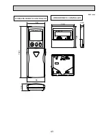
Page 43: ...43 WIRED REMOTE CONTROLLER WIRELESS REMOTE CONTROLLER 130 120 19 5 159 3 55 58 19 Unit mm ...

Page 44: ...SNAY CONNECTOR REMOTE SWITCH CONNECTOR HA TERMINAL A CONNECTOR CENTRALLY CONTROL POWER SUPPLY I B POWER SUPPLY R B TRANSMISSION INDOOR OUTDOOR RELAY DRAIN PUMP SWITCH MODEL SELECTION See table 1 SWITCH CAPACITY CORD See table 2 CONNECTOR EMERGENCY OPERATION FAN MOTOR VANE MOTOR DRAIN UP MACHINE DRAIN FLOAT SWITCH TERMINAL BLOCK Indoor unit Power option TERMINAL BLOCK INDOOR OUTDOOR CONNECTING LINE...

Page 45: ...mistor liquid Cond eva temp Thermistor AC reactor Power factor improvement Connector Lossnay LED Power supply Terminal block Remote controller transmission line Terminal block Float switch Indoor outdoor connecting line Power supply board Aux relay Switch for mode selection Switch for capacity code Connector emergency operation Drain pump Fan motor Blue Blue Red Blue Red Blue TO OUTDOOR UNIT A Blu...

Page 46: ...R OVER CURRENT RELAY INDOOR FAN MOTOR FAN MOTOR INDOOR TH2 TH1 TB2 4 5 49F 51F MF1 52FLo MAGNETIC CONTACTOR INDOOR FAN MOTOR LOW SPEED AUXILIARY RELAY X1 FERRITE CORE FB BOARD CONTROLLER INDOOR CN2L CN31 CN90 CN51 CN41 CN32 CONNECTOR DRAIN SENSOR CONNECTOR REMOTE SWITCH CONNECTOR HA TERMINAL A CONNECTOR CENTRALLY CONTROL CONNECTOR WIRELESS REMOTE CONTROLLER CONNECTOR LOSSNAY 4 Indoor and outdoor c...

Page 47: ...B12 FB21 FB22 INDOOR CONTROLLER BOARD X1 2 AUXILIARY RELAY NAME SYMBOL SNB BOARD 1 ZNR5 7 VARISTOR DSA DSR ARRESTER SW2 SWE LED1 LED POWER SUPPLY LED2 LED POWER SUPPLY REMOTE CONTROLLER LED3 LED TRANSMISSION INDOOR OUTDOOR SWITCH MODEL SELECTION SW1 SWITCH CAPACITY CORD CONNECTOR EMERGENCY OPERATION OUTDOOR UNIT TERMINAL BLOCK NAME SYMBOL TB3 TB8 CN2L CN31 CN90 CN51 CN41 CN32 CONNECTOR DRAIN SENSO...

Page 48: ...Indoor and outdoor connecting wires have poIarities make sure to match terminal numbers S1 S2 S3 for correct wirings 3 Since the outdoor side electric wiring may change be sure to check the outdoor unit electric wiring diagram for servicing 4 This diagram shows the wiring of indoor and outdoor connecting wires specification of 230V adopting superimposed system for power and signal 1 If indoor and ...

Page 49: ...ely Drain pump option CN4F Wired remote controller Terminal block Remote controller transmission line TB6 TH2 SW1 TH5 SW2 SWE LEGEND TO OUTDOOR UNIT 5 3 1 3 1 CN01 BLK ORN YLW BLU RED GRN YLW I B 1 Fig 1 I B TB2 POWER SUPPLY 1PHASE 230V 50Hz ORN ORN YLW BRN TB4 INDOOR OUTDOOR COMMUNICATION CN3C BLU L N S1 S2 S3 W B REC1 LED1 LED2 Pcb for wireless remote controller Receiving unit LED Operation indi...

Page 50: ...PPLY R B TRANSMISSION INDOOR OUTDOOR RELAY DRAIN PUMP WIRED REMOTE CONTROLLER BOARD SWITCH MODEL SELECTION See table 1 SWITCH CAPACITY CODE See table 2 CONNECTOR EMERGENCY OPERATION FAN MOTOR VANE MOTOR DRAIN LIFT UP MECHANISM DRAIN FLOAT SWITCH TERMINAL BLOCK Indoor unit Power optional parts TERMINAL BLOCK INDOOR OUTDOOR CONNECTING LINE TERMINAL BLOCK REMOTE CONTROLLER TRANSMISSION LINE REACTOR R...

Page 51: ...3 2 1 D HEATER CNC RED For PCA RP125HA X6 X5 X4 X6 X5 X4 FUSE SWE FAN WHT SW2 SW1 LED3 LED2 LED1 H2 OFF ON 1 2 1 2 1 2 1 2 1 3 1 2 WHT WHT REMOCON CN22 BLU TH1 TH2 TH5 BLU BLU BLK BLK 1 2 2 1 TB5 INTAKE CN20 RED LIQUID CN21 WHT PIPE CN29 BLK R B TB6 TRANSMISSION WIRES DC12V CN41 CN2L CN32 CN51 ROWER CNDK RED ROWER CND ORN DC13 1V CNDK RED CN2S WHT P B I B BRN YLW ORN ORN S1 S2 S3 TB4 TO OUTDOOR UN...

Page 52: ...POWER BOARD SYMBOL NAME LEGEND SYMBOL NAME SYMBOL NAME I B I B INDOOR CONTROLLER BOARD FUSE FUSE T6 3AL250V CN2L CONNECTOR LOSSNAY CN32 CONNECTOR REMOTE SWITCH CN41 CONNECTOR HA TERMINAL A CN51 CONNECTOR CENTRALLY CONTROL SW1 SWITCH MODEL SELECTION See Table 1 SW2 SWITCH CAPACITY CODE See Table 2 SWE SWITCH EMERGENCY OPERATION X4 RELAY FAN MOTOR X5 RELAY FAN MOTOR X6 RELAY FAN MOTOR X2 RELAY LOUVE...

Page 53: ... Phase Pipe Thermistor Outdoor Thermistor Heat Sink TH32 Thermistor Shell Electronic Expansion Valve Reactor CY1 CY2 Reactor Power Circuit Board Connection Terminal U V W Phase P B TABU V W Noise Filter Circuit Board Connection Terminal L Phase Connection Terminal Ground N F LI LO Connection Terminal N Phase NI NO EI E2 E3 Controller Circuit Board Switch Forced Defrost Defect History Record Reset ...

Page 54: ...pe Thermistor Outdoor Thermistor Heat Sink TH32 Thermistor Shell Electronic Expansion Valve Reactor CY1 CY2 Reactor Power Circuit Board Connection Terminal U V W Phase P B TABU V W Noise Filter Circuit Board Connection Terminal L Phase Connection Terminal Ground N F LI LO Connection Terminal N Phase NI NO EI E2 E3 Controller Circuit Board Switch Forced Defrost Defect History Record Reset Refrigera...

Page 55: ...2 LI NI EI E4 E2 E3 U POWER SUPPLY N 230V 50Hz INDOOR UNIT TB1 L N S1 S2 S3 MC 3 1 3 1 2 RED CNAC1 WHT CNAC2 RED 1 3 1 3 CN52C RED 52C 52C BLU YLW GRN YLW ORN BRN RED WHT RED BLK BLK BLK BLK DCL1 DCL CB TB1 MC MF1 MF2 21S4 63H TH3 TH33 TH4 TH6 TH7 DCL Terminal Block Power Supply Indoor Outdoor Motor for Compressor Fan Motor Solenoid Valve Four Way Valve High Pressure Switch Thermistor Outdoor Pipe...

Page 56: ...etup SW7 Switch Test Operation SW4 LED1 LED2 LED Operatiion Inspection Indicators CNM CNMNT CNVMNT Connector A Control Service Inspection Kit Connector Connect to Optional M NET Adapter Board Connector Connect to Optional M NET Adapter Board CN3S Connector Connection for Option CNDM Connector Connection for Option Contact Input CN51 Connector Connection for Option X51 X52 Relay FUSE T6 3AL250V F1 ...

Page 57: ...itch Thermistor Outdoor Pipe SC U V W TB L1 L2 L3 Connection Terminal U V W Phase Thermistor Discharge Thermistor Outdoor 2 Phase Pipe Thermistor Outdoor TH32 Thermistor Shell Fuse T15AL250V Electronic Expansion Valve Reactor ACL4 Reactor Connection Terminal L1 L2 L3 Power supply P B Power Circuit Board RS Rush Current Protect Resistor CB1 CB2 Main Smoothing Capacitor Connection Terminal Noise Fil...

Page 58: ...r 50 Heat exchanger Refrigerant GAS pipe connection Flare Refrigerant LIQUID pipe connection Flare 5 1 INDOOR UNIT PLA RP BA BA2 BA3 PEAD RP JA L PCA RP KA PCA RP HA PSA RP GA Thermistor TH2 Pipe temperature Liquid Distributor with strainer 50 Thermistor TH5 Cond Eva temperature Thermistor TH1 Room temperature Refrigerant flow in cooling Refrigerant flow in heating Strainer 50 Strainer 50 Heat exc...

Page 59: ...n cooling Refrigerant flow in heating Strainer Strainer Room temperature thermistor TH1 2 Refrigerant GAS pipe connection Brazing Refrigerant LIQUID pipe connection Brazing Condenser evaporator temperature thermistor TH5 2 Pie temperature thermistor Liquid TH2 2 Strainer Strainer Room temperature thermistor TH1 1 Refrigerant GAS pipe connection Brazing Refrigerant LIQUID pipe connection Brazing Co...

Page 60: ...ve with service port Refrigerant GAS pipe connection 15 88 5 8 PUHZ RP60VHA4 PUHZ RP71VHA4 5 2 OUTDOOR UNIT PUHZ RP35VHA4 PUHZ RP50VHA4 unit mm inch Refrigerant flow in cooling Refrigerant flow in heating Thermistor TH7 Outdoor Heat exchanger Refrigerant GAS pipe connection ø12 7 1 2F Refrigerant LIQUID pipe connection ø6 35 1 4F Stop valve Strainer 100 Power receiver Linear expansion valve B Ther...

Page 61: ...ion ø15 88 5 8 Refrigerant flow in cooling Refrigerant flow in heating PUHZ RP100VKA PUHZ RP125VKA PUHZ RP100YKA PUHZ RP125YKA PUHZ RP140VKA PUHZ RP140YKA Distributor Thermistor TH7 Outdoor Thermistor TH33 Outdoor pipe Heat exchanger Refrigerant LIQUID pipe connection 9 52 3 8 Stop valve with service port Strainer 100 Power receiver Linear Heat interchange circuit expansion valve B Linear expansio...

Page 62: ...fler Charge plug Low pressure Charge plug Higt pressure Ball valve Refrigerant GAS pipe connection 25 4 1 Refrigerant flow in cooling Refrigerant flow in heating Distributor Thermistor TH7 Heat exchanger Refrigerant LIQUID pipe 12 7 1 2 Stop valve with service port Strainer 100 Power receiver Linear expansion valve B Linear expansion valve A Strainer 100 Thermistor TH6 Thermistor TH3 High pressure...

Page 63: ... intake air dry bulb temperature D B 5 0 5 10 15 20 25 30 35 40 46 16 18 20 22 0 4 0 6 0 8 1 0 1 2 PERFORMANCE CURVES 6 Note These diagrams show the case where the operation frequency of a compressor is fixed FOR THE COMBINATION OF OUTDOOR UNIT Cooling capacity Cooling input Indoor intake air wet bulb temperature W B Indoor intake air wet bulb temperature W B ...

Page 64: ...operation frequency of a compressor is fixed Heating capacity Heating input Indoor intake air dry bulb temperature D B Indoor intake air dry bulb temperature D B Outdoor intake air wet bulb temperature W B Outdoor intake air wet bulb temperature W B ...

Page 65: ... RP71VHA4 1 00 0 997 0 991 0 985 0 979 0 973 0 970 PUHZ RP100VKA PUHZ RP100YKA 1 00 0 997 0 991 0 985 0 979 0 973 0 970 0 967 0 961 0 955 PUHZ RP125VKA PUHZ RP125YKA 1 00 0 997 0 991 0 985 0 979 0 973 0 970 0 967 0 961 0 955 PUHZ RP140VKA PUHZ RP140YKA 1 00 0 997 0 991 0 985 0 979 0 973 0 970 0 967 0 961 0 955 7 2 PUHZ RP200 250YKA Cooling capacity correction factors Outdoor unit Refrigerant pipin...

Page 66: ...ndard size 50m 30m 50m 30m 9 52 15 88 Standard size 50m 30m 9 52 19 05 50m 30m 50m 30m 6 35 12 7 9 52 15 88 Standard size 50m 30m 50m 30m 9 52 19 05 50m 30m 12 7 19 05 50m 20m 50m 20m 12 7 19 05 50m 20m RP100 RP50 2 RP71 RP35 2 RP125 RP60 2 RP140 RP71 2 6 35 12 7 9 52 15 88 12 7 19 05 Liquid pipe Gas pipe Liquid pipe Gas pipe Liquid pipe Gas pipe Liquid pipe Gas pipe Branch pipe mm B C Main pipe m...

Page 67: ...00 If the calculation produces a negative number W 0 additional charging is not necessary L1 12 7 liquid pipe length m L2 9 52 liquid pipe length m L3 6 35 liquid pipe length m Outdoor unit 2 5kg 3 5kg 5 0kg 31 40m 0 2kg 0 6kg 0 6kg 41 50m 0 4kg 1 2kg 1 2kg 51 60m 1 8kg 61 70m 71 75m 2 4kg Table 7 Additional refrigerant charging amount for pipe of standard diameter Outdoor unit Type Type Permitted...

Page 68: ...it side Liquid pipe 9 52 Gas pipe 15 88 pipe length B 20m C 15m 1 Farthest piping length 20m 15m 35m Number of bends 10 2 Corrected piping length 35m 0 3 o 10 38m 3 Capacity correction Outdoor unit side s gas pipe 19 05 Standard 15 88 1 size up Refer to 1 Capacity curves Standard size 4 Capacity Cooling capacity Standard cooling capacity o 0 89 Heating capacity Standard heating capacity o 0 98 1 C...

Page 69: ...gas pipe is 1 size smaller than standard size 5 10 15 20 25 30 35 80 Capacity ratio Corrected pipe length m 85 90 95 100 Heating RP60 RP71 12 7 Cooling RP60 RP71 12 7 2 Capacity curve for PUHZ RP35 50 models When gas pipe is 1 size smaller than standard size 5 10 15 20 25 30 35 80 Capacity ratio Corrected pipe length m 85 90 95 100 Heating RP35 RP50 9 52 Cooling RP35 9 52 Cooling RP50 9 52 Cooling...

Page 70: ... pipe length exceeds 20m Liquid pipe mm Gas pipe mm O D Thick ness O D Thick ness RP200 RP250 9 52 t0 8 12 7 t0 8 15 88 t1 0 19 05 t1 0 20m 20m 20m 20m 22 2 t1 0 50m 30m 50m 30m 25 4 t1 0 Standard size 120m 30m 120m 30m 28 58 t1 0 120m 30m 120m 30m 19 05 t1 0 20m 20m 20m 20m 22 2 t1 0 50m 30m 50m 30m 25 4 t1 0 120m 30m Standard size 120m 30m 22 2 t1 0 50m 20m 50m 20m 25 4 t1 0 50m 20m 50m 20m 28 5...

Page 71: ... 1 Capacity curves 1 Standard size 2 Capacity curves 2 When the gas pipe s diameter is 1 size smaller than the standard size 3 Capacity curves 3 When the gas pipe s diameter is 2 size smaller than the standard size Cooling Heating RP200 RP250 RP200 250 5 10 15 20 25 30 35 40 45 50 55 60 65 70 75 80 85 90 95 100 105 110 115 125 120 70 75 80 85 90 95 100 Corrected pipe length m Capacity ratio Heatin...

Page 72: ...50m 30m 50m 30m 50m 30m 120m 30m 120m 30m 120m 30m 120m 30m 120m 30m 120m 30m 120m 30m 120m 30m 120m 30m 120m 30m 50m 20m 50m 20m 50m 20m 50m 20m 50m 20m 50m 20m 50m 20m 50m 20m 50m 20m 50m 20m 50m 20m 50m 20m 20m 20m 20m 20m 20m 20m 50m 30m 50m 30m 50m 30m 20m 20m 20m 20m 20m 20m 50m 30m 50m 30m 50m 30m 120m 30m 120m 30m 120m 30m 120m 30m 120m 30m 120m 30m 120m 30m 120m 30m 120m 30m 120m 30m 50m ...

Page 73: ... A B C D E RP200 120 m and less 100 m and less 30 m and less PR250 B C or B D or Outdoor unit B E or C D or Number of pipe bends C E or D E RP200 8 m and less Within 15 RP250 Table 6 Lowered cooling capacity by the smaller gas pipe diameter 5m and less 6 10m 11 20m 21 30m 31 40m 41 50m 100 100 95 95 88 88 83 83 79 79 75 100 100 88 88 77 Pipe length gas pipe 22 2 gas pipe 19 05 Cooling capacity rat...

Page 74: ...erant is not necessary charge less When the extension pipe length main piping branch piping exceeds 20m charge the amount of refrigerant that is obtained by the formula shown in Table 7 If the calculation produces a negative number i e a minus charge additional charging is not necessary Note Apply 0 to L1 L2 L3 and L4 which correspond to the liquid pipe size that are not used Correcting the capaci...

Page 75: ...r speed m sec 2 9 4 2 Coverage range m 7 9 13 2 PKA RP35HAL PKA RP50HAL Airflow m3 min 12 12 Air speed m sec 6 1 6 1 Coverage range m ft 10 8 35 4 10 8 35 4 PKA RP60KAL PKA RP71KAL PKA RP100KAL Airflow m3 min 22 22 26 Air speed m sec 6 0 6 0 6 8 Coverage range m ft 14 3 46 9 14 3 46 9 16 1 52 8 PSA RP71GA PSA RP100GA PSA RP125GA PSA RP140GA Airflow m3 min 18 31 33 35 Air speed m sec 2 6 4 5 4 8 4 ...

Page 76: ...ng those of the optional multi function casement When installing the optional multi function casement add 135 mm to the dimensions marked on the figure When installing the branch ducts be sure to insulate adequately Otherwise condensation and dripping may occur Branch duct hole 14 2 8 burring hole Indoor unit 150 cut out hole Fresh air intake hole 175 burring hole pitch Drain pipe Fresh air intake...

Page 77: ...ure Pa Static pressure Pa Static pressure Pa 200 150 100 50 0 50 0 2 4 6 8 2 inlet 1 inlet At using multi function casement standard filter 200 150 100 50 0 50 0 2 4 6 8 2 inlet 1 inlet At using multi function casement high efficiency filter 200 150 100 50 0 50 0 1 2 3 4 5 6 2 inlet 1 inlet Airflow rate m3 min Airflow rate m3 min Airflow rate m3 min Airflow rate m3 min Airflow rate m3 min Airflow ...

Page 78: ...onnector 5 Branch duct and change of outlet numbers 4 way air flow and branch duct Branch duct should be connected to one of the branch duct holes on the main unit Branch duct Air intake Air outlet 3 way air flow and branch duct Close the outlet on the side of branch duct and air flows in 3 directions Branch duct Air intake Air outlet Air outlet closed position Air outlet closed position 2 way air...

Page 79: ...and 2 way airflow 2 way airflow horizontal vane Rectangular duct 0 10 20 30 0 2 High Low High Low High Low High Low High Low 4 6 8 Airflow rate m3 min 0 2 4 6 8 Airflow rate m3 min Airflow rate m3 min Airflow rate m3 min Static pressure Pa 0 10 20 30 Static pressure Pa 0 10 20 30 40 50 60 70 80 0 2 4 6 8 10 Airflow rate m3 min 0 2 4 6 8 10 Static pressure Pa 0 10 20 30 40 50 60 70 80 Static pressu...

Page 80: ...tatic pressure Pa High Low High Low Duct Duct Close Close Use 1 of the 2 duct holes on the indoor unit Airflow rate of PLA RP100BA 3 PLA RP140BA2 can be calculated from the airflow rate based on the characteristic of the duct for PLA RP125BA 2 Use the optional air outlet shutter plate PAC SH51SP E for 3 way and 2 way airflow 0 10 20 30 40 50 60 70 80 90 100 0 2 4 6 8 10 12 0 10 20 30 40 50 60 70 8...

Page 81: ... amount of fresh air intake m3 min A Static pressure loss of fresh air intake duct system with airflow amount Q Pa B Forced static pressure at air conditioner inlet with airflow amount Q Pa C Static pressure of booster fan with airflow amount Q Pa D Static pressure loss increase amount of fresh air intake duct system for airflow amount Q Pa E Static pressure of indoor unit with airflow amount Q Pa...

Page 82: ... rate m3 min 7 9 11 13 15 17 19 21 Airflow rate m3 min 7 9 11 13 15 17 19 21 Airflow rate m3 min External static pressure Pa 60 70 50 40 30 20 10 0 7 9 11 13 15 17 19 21 Airflow rate m3 min 0 External static pressure Pa 80 90 100 110 120 130 140 150 160 170 70 40 50 60 10 20 30 0 External static pressure Pa 60 70 80 90 50 40 30 20 10 0 External static pressure Pa 7 9 11 13 15 17 19 21 Airflow rate...

Page 83: ...30 20 10 0 External static pressure Pa Airflow rate m3 min 60 70 80 50 40 30 20 10 0 External static pressure Pa 80 90 100 110 120 130 140 150 160 170 180 70 40 50 60 10 20 30 0 External static pressure Pa 0 60 70 80 90 100 50 40 30 20 10 External static pressure Pa 9 14 19 Airflow rate m3 min 60 70 80 90 100 110 120 130 50 40 30 20 10 0 External static pressure Pa Rated point High Middle Low Limi...

Page 84: ... 30 Airflow rate m3 min 60 50 40 30 20 10 0 External static pressure Pa 10 15 20 25 30 Airflow rate m3 min 60 70 50 40 30 20 10 0 External static pressure Pa 80 90 100 110 120 130 140 150 160 170 70 40 50 60 10 20 30 0 External static pressure Pa 0 60 70 80 90 50 40 30 20 10 External static pressure Pa 10 15 20 25 30 Airflow rate m3 min 60 70 80 90 100 110 120 50 40 30 20 10 0 External static pres...

Page 85: ...xternal static pressure Pa 10 15 20 25 30 Airflow rate m3 min 60 70 80 90 50 40 30 20 10 0 External static pressure Pa 10 80 90 100 110 120 130 140 150 160 170 180 70 40 50 60 10 20 30 0 External static pressure Pa 10 15 20 25 30 Airflow rate m3 min 0 60 70 80 90 100 50 40 30 20 10 External static pressure Pa 10 15 20 25 30 Airflow rate m3 min 60 70 80 90 100 110 120 130 50 40 30 20 10 0 External ...

Page 86: ...w rate m3 min 60 70 80 90 100 50 40 30 20 10 0 External static pressure Pa 15 20 25 30 35 40 45 Airflow rate m3 min 10 80 90 100 110 120 130 140 150 160 170 180 190 200 70 40 50 60 10 20 30 0 External static pressure Pa 10 15 20 25 30 35 40 45 Airflow rate m3 min 0 60 70 80 90 100 110 120 50 40 30 20 10 External static pressure Pa 10 15 20 25 30 35 40 45 Airflow rate m3 min 60 70 80 90 100 110 120...

Page 87: ...ted point High Middle Low Limit 20 25 30 35 40 45 Airflow rate m3 min 15 80 90 100 110 120 130 140 150 160 170 180 190 200 210 220 230 70 40 50 60 10 20 30 0 External static pressure Pa Rated point High Middle Low Limit 15 20 25 30 35 40 45 Airflow rate m3 min 70 60 50 40 30 20 10 0 External static pressure Pa Rated point High Middle Low Limit 15 20 25 30 35 40 45 Airflow rate m3 min 60 70 80 90 1...

Page 88: ...25 30 35 40 45 Airflow rate m3 min 15 80 90 100 110 120 130 140 150 160 170 180 190 200 210 220 230 240 70 40 50 60 10 20 30 0 External static pressure Pa 15 20 25 30 35 40 45 Airflow rate m3 min 70 60 50 40 30 20 10 0 External static pressure Pa 15 20 25 30 35 40 50 45 Airflow rate m3 min 60 70 80 90 100 50 40 30 20 10 0 External static pressure Pa 15 20 25 30 35 40 45 Airflow rate m3 min 0 60 70...

Page 89: ... 0 110 0 120 0 130 0 90 0 Pa Pa Pa External static pressure Airflow CMM 0 50 100 150 200 300 250 110 0 100 0 120 0 130 0 140 0 150 0 160 0 170 0 Pa External static pressure Airflow CMM 0 50 100 150 200 350 300 250 Hi Lo 45 0 50 0 55 0 60 0 65 0 70 0 Hi Lo 0 50 100 150 200 250 300 0 50 100 150 200 250 60 0 65 0 70 0 75 0 80 0 85 0 90 0 External static pressure Airflow Airflow CMM CMM External stati...

Page 90: ...SHOLD OF HEARING FOR CONTINUOUS NOISE NC 60 NC 50 NC 40 NC 30 NC 20 NC 70 BAND CENTER FREQUENCIES Hz PLA RP60BA PLA RP71BA PLA RP71BA2 NOTCH SPL dB LINE High 32 Medium1 31 Medium2 29 Low 28 NOTCH SPL dB LINE High 34 Medium1 32 Medium2 30 Low 28 90 80 70 60 50 40 30 20 10 63 125 250 500 1000 2000 4000 8000 APPROXIMATE THRESHOLD OF HEARING FOR CONTINUOUS NOISE NC 60 NC 50 NC 40 NC 30 NC 20 NC 70 BAN...

Page 91: ...ND SOUND PRESSURE LEVEL dB 0 dB 0 0002 μbar BAND CENTER FREQUENCIES Hz PLA RP140BA2 NOTCH SPL dB LINE High 44 Medium1 42 Medium2 39 Low 36 90 80 70 60 50 40 30 20 10 63 125 250 500 1000 2000 4000 8000 APPROXIMATE THRESHOLD OF HEARING FOR CONTINUOUS NOISE NC 60 NC 50 NC 40 NC 30 NC 20 NC 70 OCTAVE BAND SOUND PRESSURE LEVEL dB 0 dB 0 0002 μbar BAND CENTER FREQUENCIES Hz 90 80 70 60 50 40 30 20 10 63...

Page 92: ... 23 26 29 23 27 30 24 28 31 26 29 33 29 33 37 PEAD RP50JA L 25 30 34 26 31 35 28 32 36 29 33 37 31 35 39 PEAD RP60JA L 25 28 32 25 29 33 26 30 34 27 31 35 29 34 38 PEAD RP71JA L 25 29 34 26 30 34 27 31 35 28 32 36 30 35 39 PEAD RP100JA L 28 33 38 29 34 38 30 35 39 31 36 40 34 40 43 PEAD RP125JA L 31 36 40 33 36 40 33 37 41 34 39 42 37 41 45 PEAD RP140JA L 33 37 43 34 38 43 34 39 44 36 40 45 38 42 ...

Page 93: ...us noise NC 60 NC 50 NC 40 NC 30 NC 20 NC 70 OCTAVE BAND SOUND PRESSURE LEVEL dB 0 dB 0 0002 μ bar BAND CENTER FREQUENCIES Hz Approximate minimum audible limit on continuous noise Approximate minimum audible limit on continuous noise External static pressure 100Pa External static pressure 150Pa High Middle Low 80 70 60 50 40 30 20 10 0 63 125 250 500 1000 2000 4000 8000 NC 60 NC 50 NC 40 NC 30 NC ...

Page 94: ...it on continuous noise NC 60 NC 50 NC 40 NC 30 NC 20 NC 70 OCTAVE BAND SOUND PRESSURE LEVEL dB 0 dB 0 0002 μ bar BAND CENTER FREQUENCIES Hz Approximate minimum audible limit on continuous noise Approximate minimum audible limit on continuous noise External static pressure 100Pa External static pressure 150Pa High Middle Low 80 70 60 50 40 30 20 10 0 63 125 250 500 1000 2000 4000 8000 NC 60 NC 50 N...

Page 95: ...us noise NC 60 NC 50 NC 40 NC 30 NC 20 NC 70 OCTAVE BAND SOUND PRESSURE LEVEL dB 0 dB 0 0002 μ bar BAND CENTER FREQUENCIES Hz Approximate minimum audible limit on continuous noise Approximate minimum audible limit on continuous noise External static pressure 100Pa External static pressure 150Pa High Middle Low 80 70 60 50 40 30 20 10 0 63 125 250 500 1000 2000 4000 8000 NC 60 NC 50 NC 40 NC 30 NC ...

Page 96: ...it on continuous noise NC 60 NC 50 NC 40 NC 30 NC 20 NC 70 OCTAVE BAND SOUND PRESSURE LEVEL dB 0 dB 0 0002 μ bar BAND CENTER FREQUENCIES Hz Approximate minimum audible limit on continuous noise Approximate minimum audible limit on continuous noise External static pressure 100Pa External static pressure 150Pa High Middle Low 80 70 60 50 40 30 20 10 0 63 125 250 500 1000 2000 4000 8000 NC 60 NC 50 N...

Page 97: ...it on continuous noise NC 60 NC 50 NC 40 NC 30 NC 20 NC 70 OCTAVE BAND SOUND PRESSURE LEVEL dB 0 dB 0 0002 μ bar BAND CENTER FREQUENCIES Hz Approximate minimum audible limit on continuous noise Approximate minimum audible limit on continuous noise External static pressure 100Pa External static pressure 150Pa High Middle Low 80 70 60 50 40 30 20 10 0 63 125 250 500 1000 2000 4000 8000 NC 60 NC 50 N...

Page 98: ...it on continuous noise NC 60 NC 50 NC 40 NC 30 NC 20 NC 70 OCTAVE BAND SOUND PRESSURE LEVEL dB 0 dB 0 0002 μ bar BAND CENTER FREQUENCIES Hz Approximate minimum audible limit on continuous noise Approximate minimum audible limit on continuous noise External static pressure 100Pa External static pressure 150Pa High Middle Low 80 70 60 50 40 30 20 10 0 63 125 250 500 1000 2000 4000 8000 NC 60 NC 50 N...

Page 99: ...it on continuous noise NC 60 NC 50 NC 40 NC 30 NC 20 NC 70 OCTAVE BAND SOUND PRESSURE LEVEL dB 0 dB 0 0002 μ bar BAND CENTER FREQUENCIES Hz Approximate minimum audible limit on continuous noise Approximate minimum audible limit on continuous noise External static pressure 100Pa External static pressure 150Pa High Middle Low 80 70 60 50 40 30 20 10 0 63 125 250 500 1000 2000 4000 8000 NC 60 NC 50 N...

Page 100: ... 63 125 250 500 1k 2k 4k 8k NC 60 NC 50 Octave band pressure level dB 0dB 20μPa NC 40 Octave band center frequencies Hz NC 20 NC 30 High Low Approximate minimum audible limit on continuous noise UNIT WALL 1m 1m MICROPHONE PKA RP35HAL PKA RP50HAL 10 0 15 0 20 0 25 0 30 0 35 0 40 0 45 0 50 0 55 0 60 0 65 0 70 0 63 125 250 500 1k 2k 4k 8k NC 60 NC 50 Approximate minimum audible limit on continuous no...

Page 101: ...33 LINE 90 80 70 60 50 40 30 20 10 63 125 250 500 1000 2000 4000 8000 APPROXIMATE THRESHOLD OF HEARING FOR CONTINUOUS NOISE NC 60 NC 50 NC 40 NC 30 NC 20 NC 70 BAND CENTER FREQUENCIES Hz 90 80 70 60 50 40 30 20 10 63 125 250 500 1000 2000 4000 8000 APPROXIMATE THRESHOLD OF HEARING FOR CONTINUOUS NOISE NC 60 NC 50 NC 40 NC 30 NC 20 NC 70 BAND CENTER FREQUENCIES Hz NOTCH High Medium1 Medium2 Low SPL...

Page 102: ...REQUENCIES Hz OCTAVE BAND SOUND PRESSURE LEVEL dB 0 dB 0 0002 μbar NOTCH High Medium1 Medium2 Low SPL dB 48 45 43 41 LINE PCA RP125KA PCA RP140KA 90 80 70 60 50 40 30 20 10 63 125 250 500 1000 2000 4000 8000 APPROXIMATE THRESHOLD OF HEARING FOR CONTINUOUS NOISE NC 60 NC 50 NC 40 NC 30 NC 20 NC 70 BAND CENTER FREQUENCIES Hz OCTAVE BAND SOUND PRESSURE LEVEL dB 0 dB 0 0002 μbar PCA RP71HA NOTCH High ...

Page 103: ...ND SOUND PRESSURE LEVEL dB 0 dB 0 0002 μbar PSA RP100GA NOTCH High Low SPL dB 49 44 LINE 90 80 70 60 50 40 30 20 10 63 125 250 500 1000 2000 4000 8000 APPROXIMATE THRESHOLD OF REARING FOR CONTINUOUS NOISE NC 60 NC 50 NC 40 NC 30 NC 20 NC 70 BAND CENTER FREQUENCIES Hz OCTAVE BAND SOUND PRESSURE LEVEL dB 0 dB 0 0002 μbar PSA RP125GA NOTCH High Low SPL dB 51 46 LINE 90 80 70 60 50 40 30 20 10 63 125 ...

Page 104: ...RESSURE LEVEL dB 0 dB 0 0002 μbar BAND CENTER FREQUENCIES Hz PUHZ RP60VHA4 PUHZ RP71VHA4 COOLING MODE HEATING 47 SPL dB 48 LINE 90 80 70 60 50 40 30 20 10 63 125 250 500 1000 2000 4000 8000 APPROXIMATE THRESHOLD OF HEARING FOR CONTINUOUS NOISE OCTAVE BAND SOUND PRESSURE LEVEL dB 0 dB 0 0002 μbar BAND CENTER FREQUENCIES Hz NC 60 NC 50 NC 40 NC 30 NC 20 NC 70 PUHZ RP100VKA PUHZ RP100YKA COOLING MODE...

Page 105: ...5 250 500 1000 2000 4000 8000 APPROXIMATE THRESHOLD OF HEARING FOR CONTINUOUS NOISE OCTAVE BAND SOUND PRESSURE LEVEL dB 0 dB 0 0002 μbar BAND CENTER FREQUENCIES Hz NC 60 NC 50 NC 40 NC 30 NC 20 NC 70 PUHZ RP200YKA COOLING MODE HEATING 58 SPL dB 59 LINE 90 80 70 60 50 40 30 20 10 63 125 250 500 1000 2000 4000 8000 APPROXIMATE THRESHOLD OF HEARING FOR CONTINUOUS NOISE OCTAVE BAND SOUND PRESSURE LEVE...

Page 106: ...r elevation panel PLP 6BAJ i see sensor corner panel PAC SA1ME E Wireless signal receiver PAR SA9FA E Space panel PAC SH48AS E Air outlet shutter plate PAC SH51SP E Multi function casement PAC SH53TM E Flange for fresh air intake PAC SH65OF E High efficiency filter element PAC SH53TM E is needed PAC SH59KF E Wireless remote controller kit PAR SL94B E PCA RP KA Drain pump PAC SH83DM E PCA RP50KA PA...

Page 107: ...50 PAC SH63AG E PUHZ RP60 71 PAC SH95AG E PUHZ RP100 250 Drain pan PAC SG63DP E PUHZ RP35 50 PAC SG64DP E PUHZ RP60 71 PAC SH97DP E PUHZ RP100 250 Filter dryer 6 35 PAC SG81DR E PUHZ RP35 50 9 52 PAC SG82DR E PUHZ RP60 200 12 7 PAC SG85DR E PUHZ RP250 Distribution pipe Twin MSDD 50TR E PUHZ RP71 140 MSDD 50WR E PUHZ RP200 250 Triple MSDT 111R E PUHZ RP140 250 Quadruple MSDF 1111R E PUHZ RP200 250 ...

Page 108: ...UNOUCHI CHIYODA KU TOKYO 100 8310 JAPAN CCopyright 2009 MITSUBISHI ELECTRIC ENGINEERING CO LTD Distributed in Jul 2009 No OCS16 PDF 6 Made in Japan New publication effective Jul 2009 Specifications subject to change without notice TM ...

Reviews: