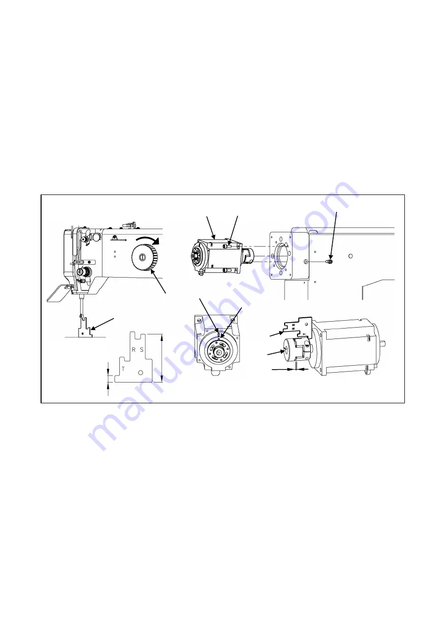
2-5. Installation of the spindle motor
(1) If the spindle motor (No.1) has been removed from the machine for the adjustment or the like, fix the
spindle motor as the procedure described below.
(2) Set the pin (No.3) position of the bushing to the motor mark (No.2).
(3) Adjust the clearance between the motor and the coupling (No.4). Use the part measuring 7mm on the
gauge (No.5). Position Bolt “A” (No.6) in the below described position when reinstalling the coupling to
the machine top shaft. Make sure the clearance of the coupling is from 2.0 to 3.2mm.
(4) Turn the pulley (No.8) in the direction of the arrow then, slip the gauge (No.5) in between the needle
bar and the needle plate. Use the part of S side (50.1mm) on the gauge.
(5) Be careful not to make the motor turn and fit the coupling to the upper shaft, and then tighten the bolt
A (No.6) first and the bolt B (No.7) second.
<1>: Spindle motor <2>: Motor mark <3>: Pin <4>: Coupling <5>: Gauge <6>: Bolt A
<7>: Bolt B <8>: Pulley
<1>
<5>
<3>
<2>
<4>
<7>
<6>
<5>
<8>
7
mm
50.
1m
m
2.0~3.2mm
- 4 -
Summary of Contents for PLK-G10050
Page 11: ...MEMO ...
Page 12: ...Printed in Japan ...


